Icon

How to Configure a Litz Coil Simulation in COMSOL

Learn how to use the Application Builder, define parameters, configure explicit selections, and set up Magnetic Fields physics for Litz coil simulations in COMSOL.

By Praveen Mukati

This guide covers how to set up a 2D Axisymmetric Litz Planar Coil simulation in COMSOL Multiphysics. You will learn to automate mesh parameterization using the Application Builder, define precise explicit selections for dense coil bundles, assign materials, and configure the Magnetic Fields (mf) physics interface.

This workflow is intended for simulation engineers, researchers, and COMSOL users dealing with complex electromagnetic geometries (like Litz wire bundles) where manually defining mesh and physics iterations is impractical.

Developing and Running Custom Methods

For models with hundreds of individual strands, using a custom Java method via the Application Builder saves time by automating repetitive parameter assignments (like mesh sizing).
1
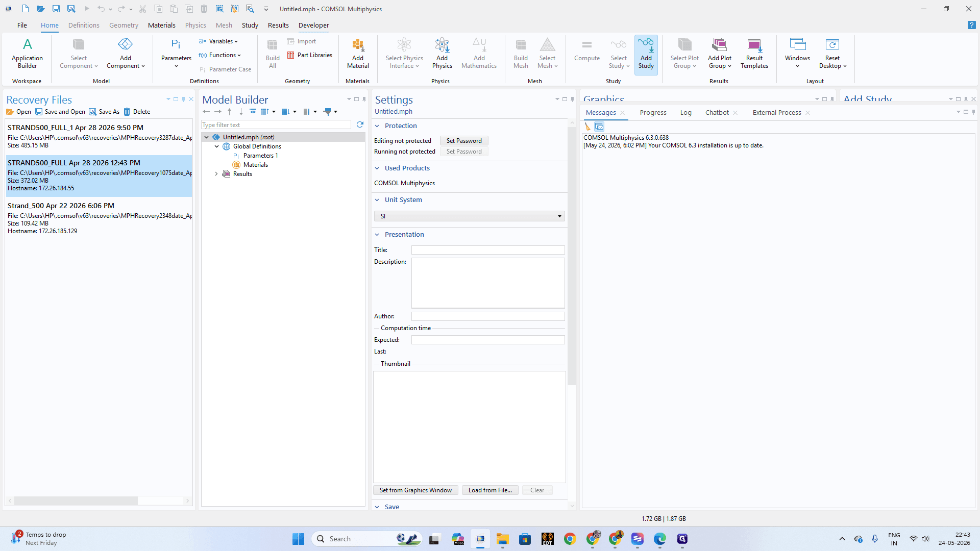
Click the Developer tab in the main ribbon menu.
Step #1: Click the Developer tab in the main ribbon menu.
2
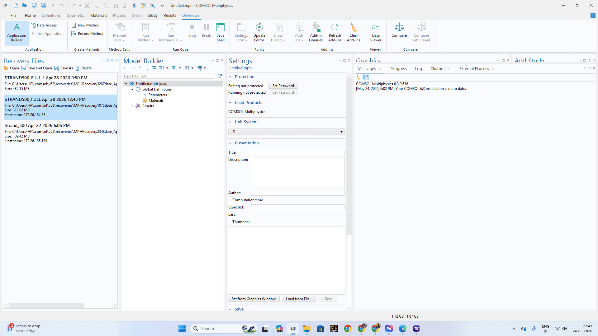
Click Application Builder to switch to the development environment.
Step #2: Click Application Builder to switch to the development environment.
3
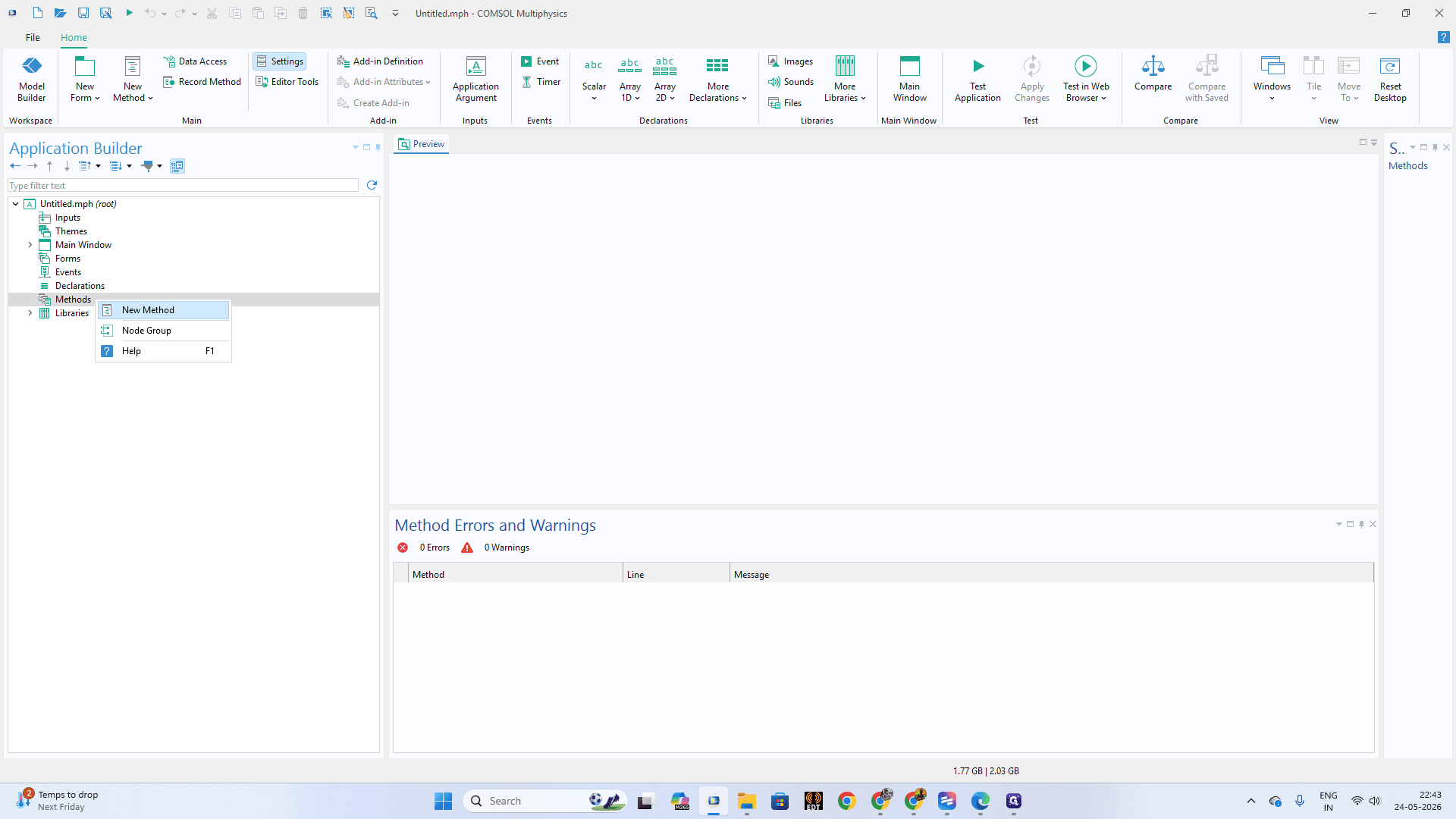
Right-click on Methods in the application tree and select New Method.
Step #3: Right-click on Methods in the application tree and select New Method.
4
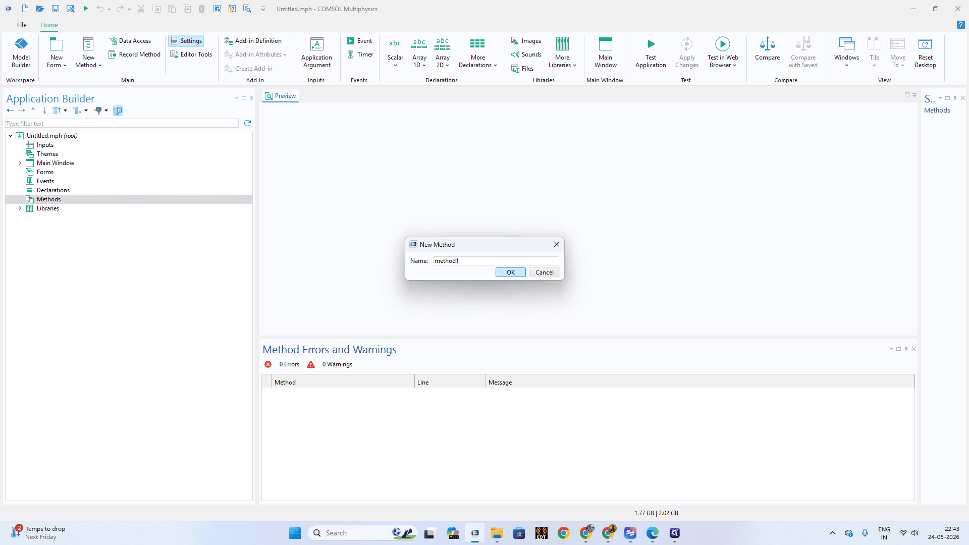
Enter a name for the method (e.g., method1) in the dialog box and click OK.
Step #4: Enter a name for the method (e.g., method1) in the dialog box and click OK.
5
In the central code editor pane, define your simulation parameters (such as mesh("mesh1") iterations) to apply sizing logic across the Litz strands.
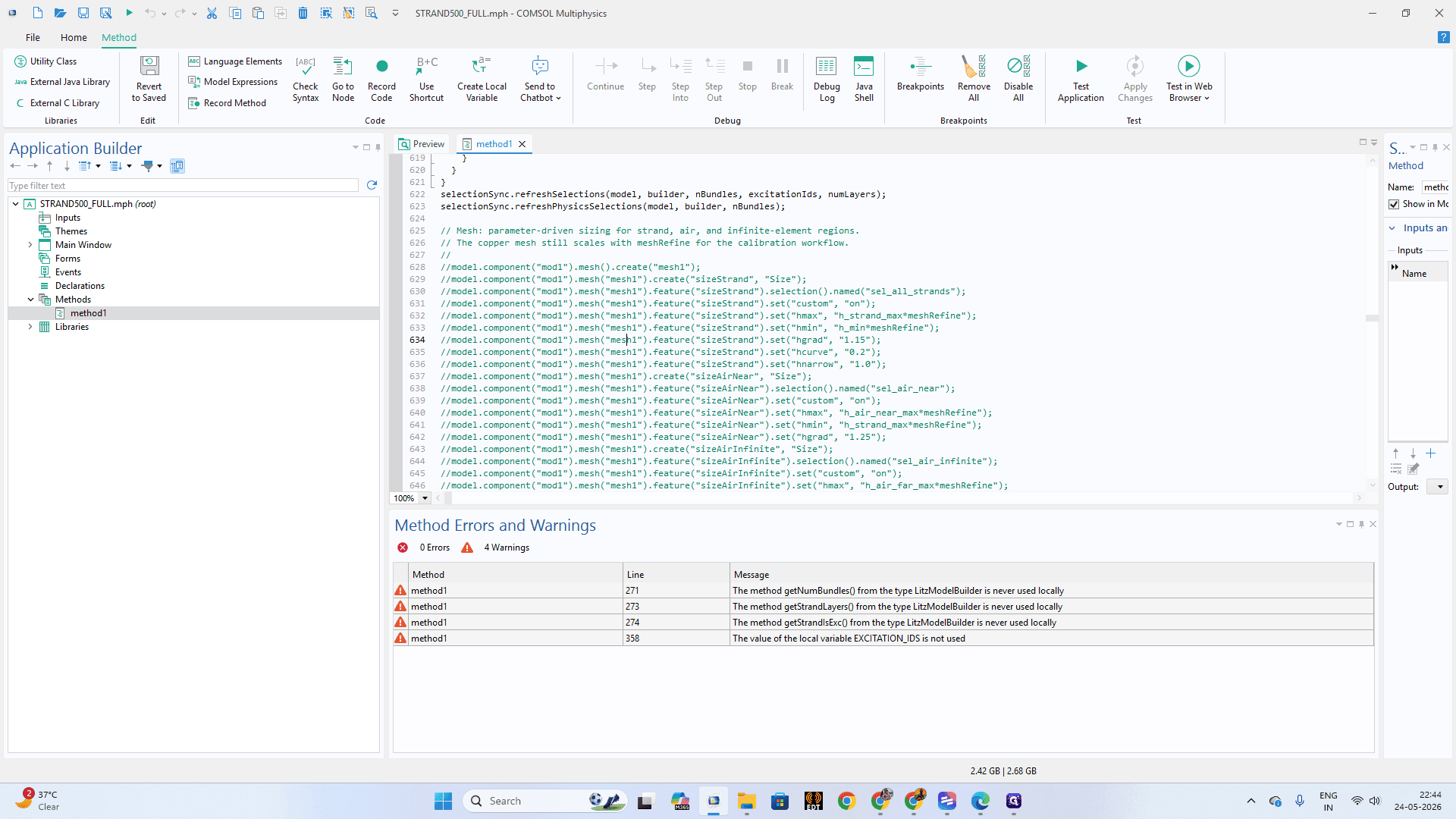
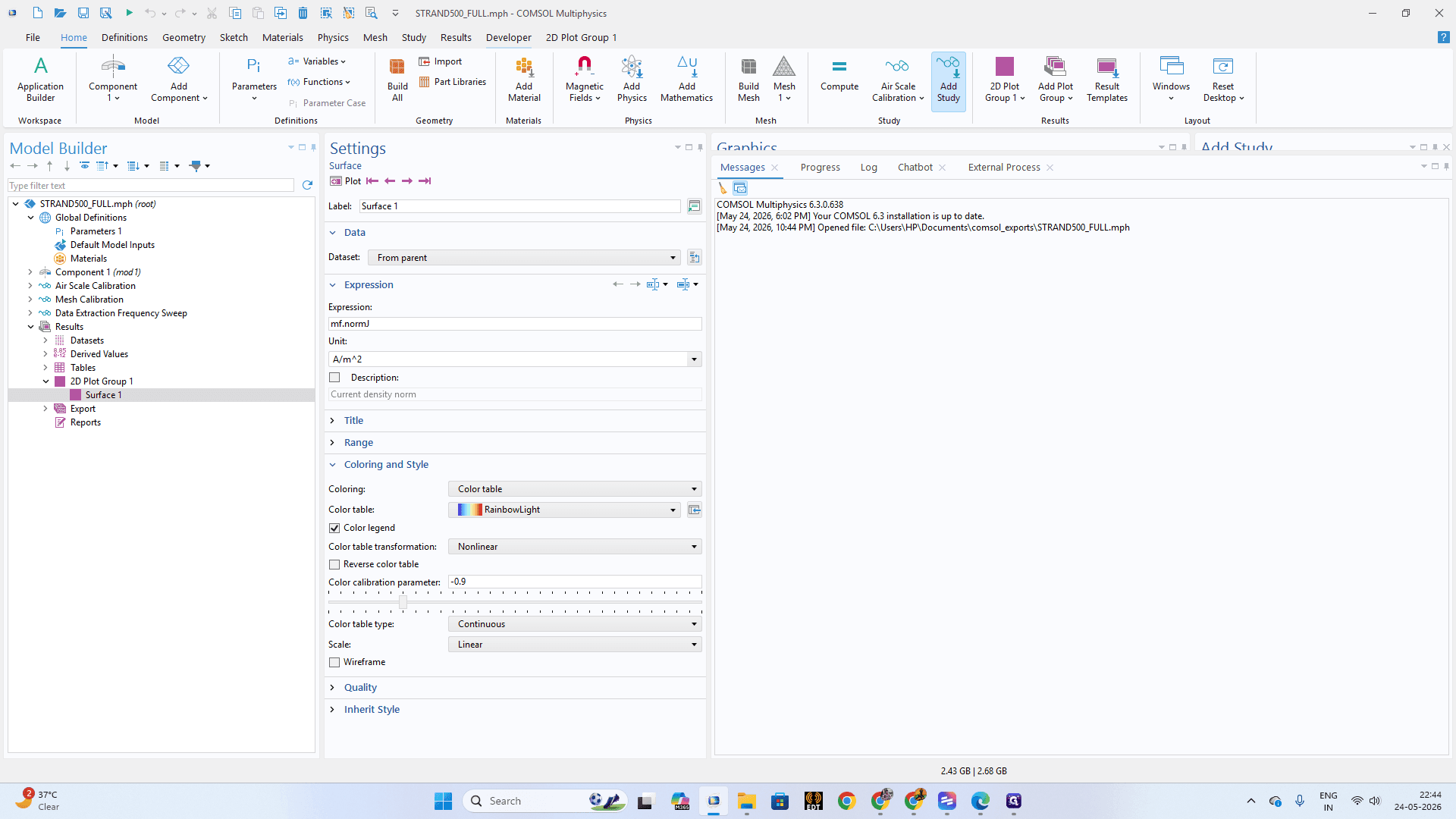
Step #5: In the central code editor pane, define your simulation parameters (such as mesh("mesh1") iterations) to apply sizing logic across the Litz strands.
6
Once your code is ready, return to the Developer tab in the ribbon.
Step #6: Once your code is ready, return to the Developer tab in the ribbon.
7
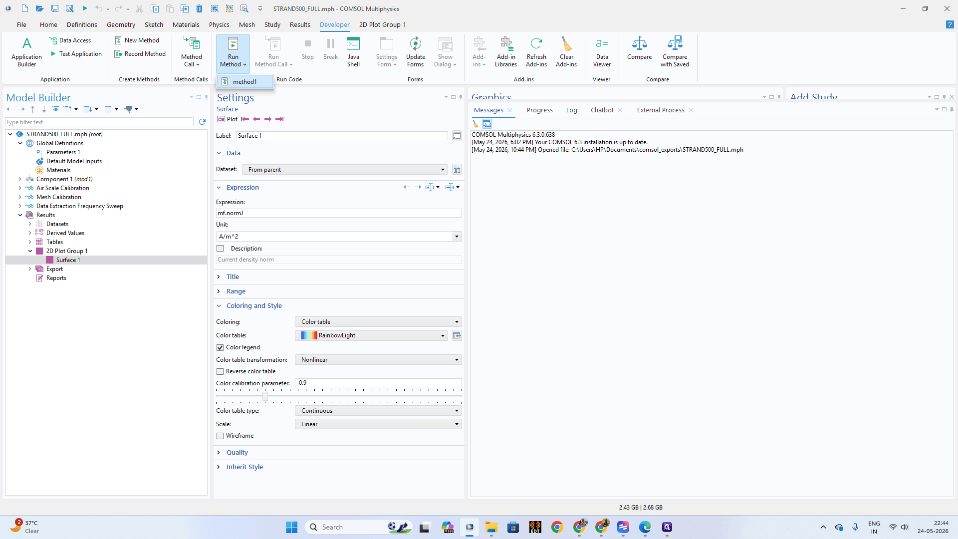
Click Run Method and select the method you just created.
Step #7: Click Run Method and select the method you just created.
8
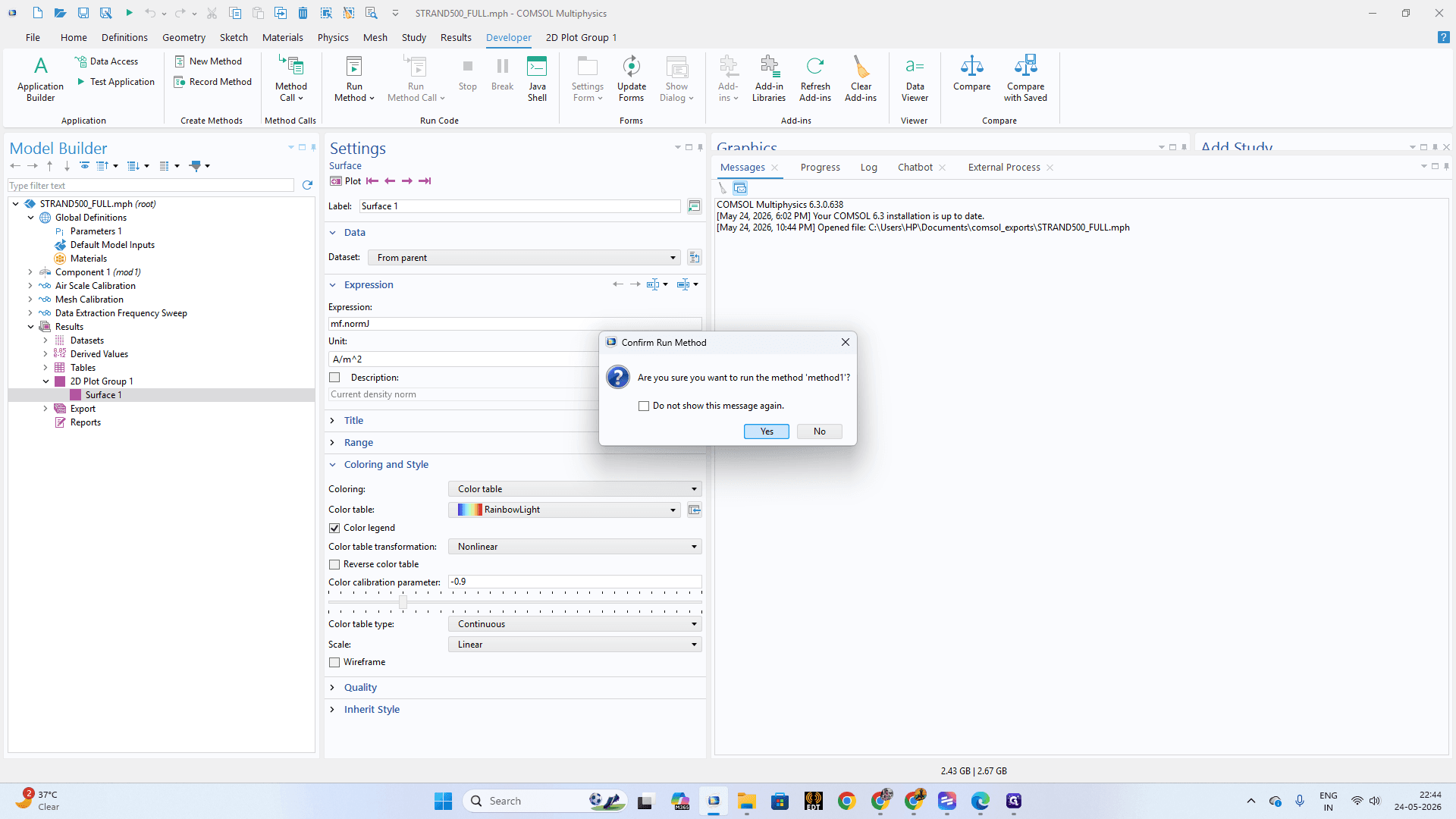
Click Yes on the confirmation prompt to execute the method.
Step #8: Click Yes on the confirmation prompt to execute the method.
9
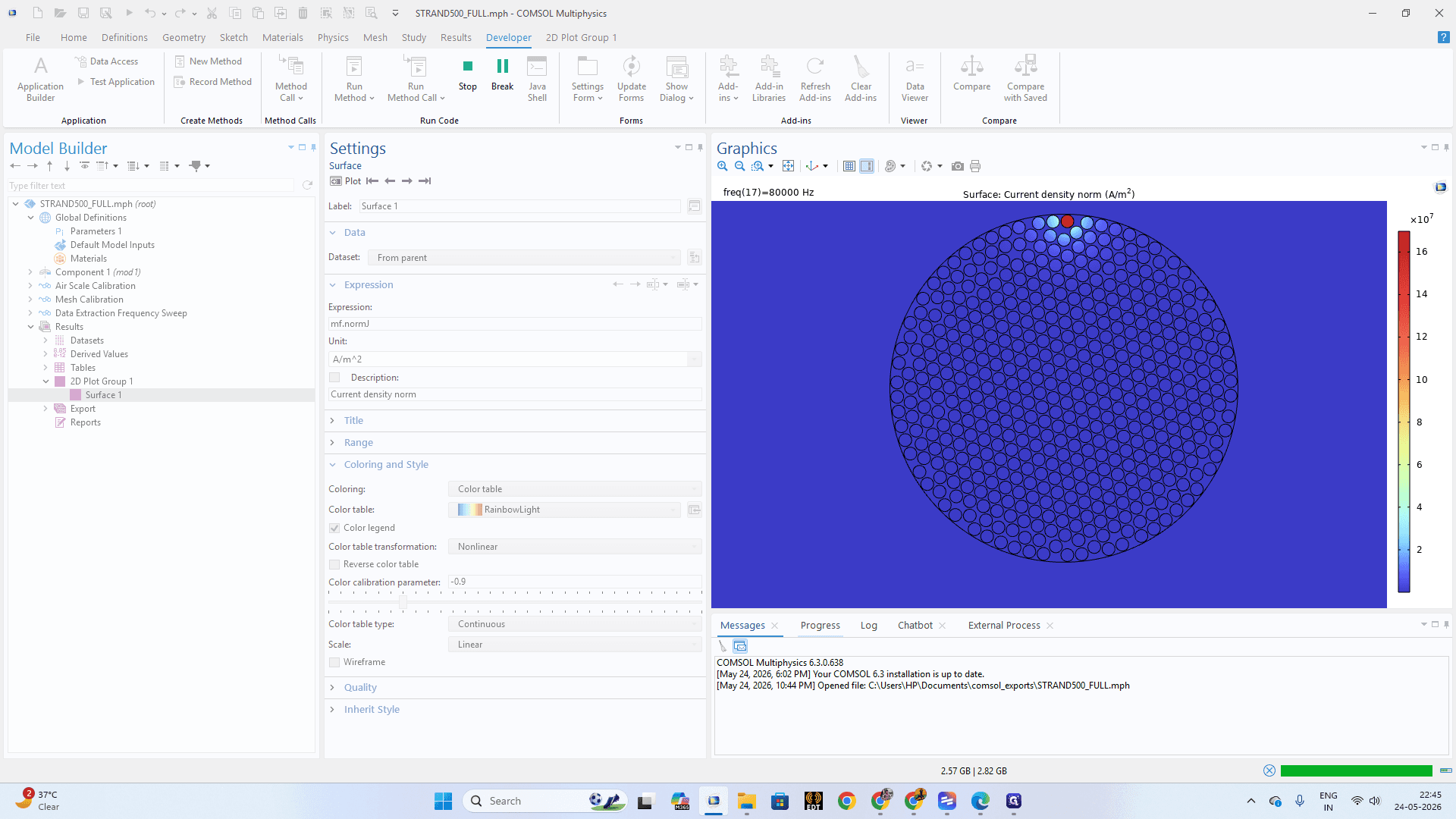
Click on the Progress tab at the bottom of the workspace to monitor the script execution until it hits 100%.
Step #9: Click on the Progress tab at the bottom of the workspace to monitor the script execution until it hits 100%.

Configuring Global Parameters

Ensure your physical properties are mathematically defined before mapping them to components.

10
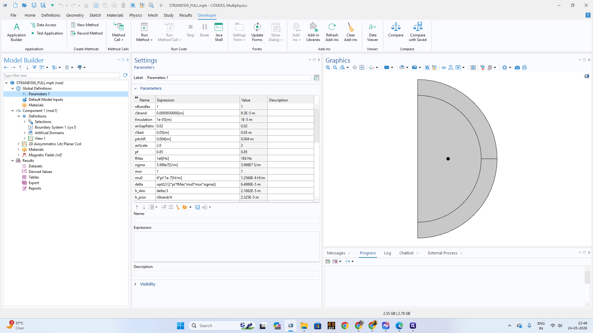
Open the Parameters table in your Settings window and enter dimension values, such as 0.0000930000 for h_prox.
Step #10: Open the Parameters table in your Settings window and enter dimension values, such as 0.0000930000 for h_prox.
11
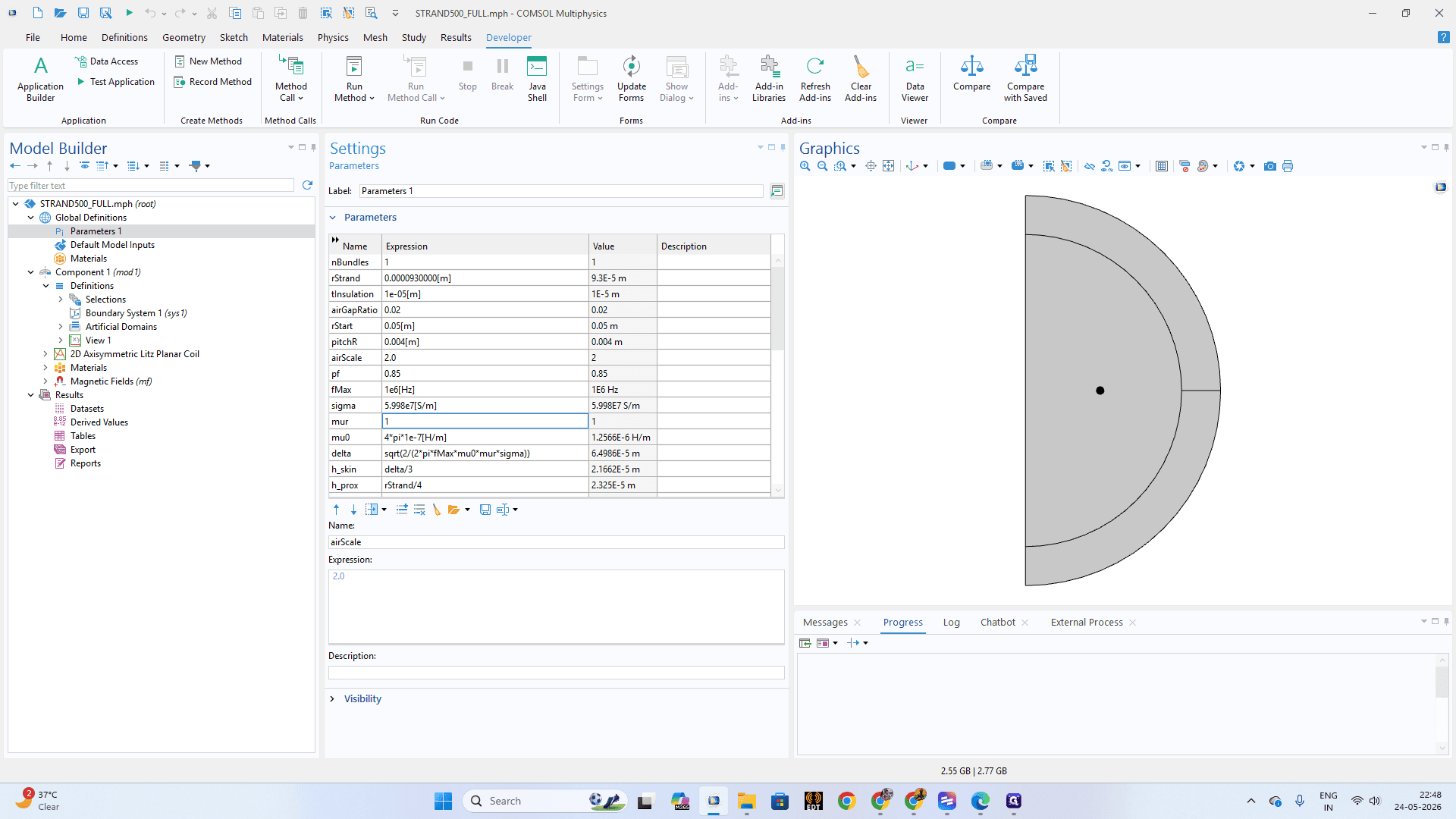
Double-click on the value cell for the mur (relative permeability) parameter.
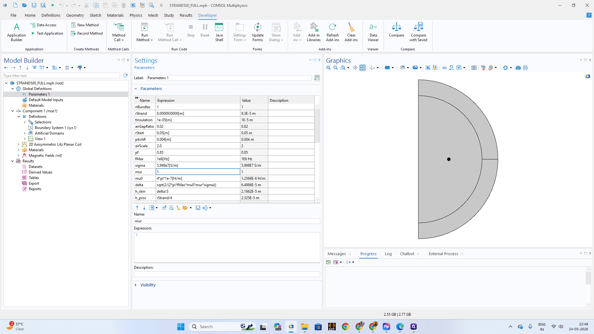
Step #11: Double-click on the value cell for the mur (relative permeability) parameter.
12
Set its value to 1 and press Enter to save.
Step #12: Set its value to 1 and press Enter to save.

Defining Geometric Selections and Materials

Grouping entities into Explicit selections makes it much easier to assign physics properties to highly repetitive geometries like Litz wire strands.
13
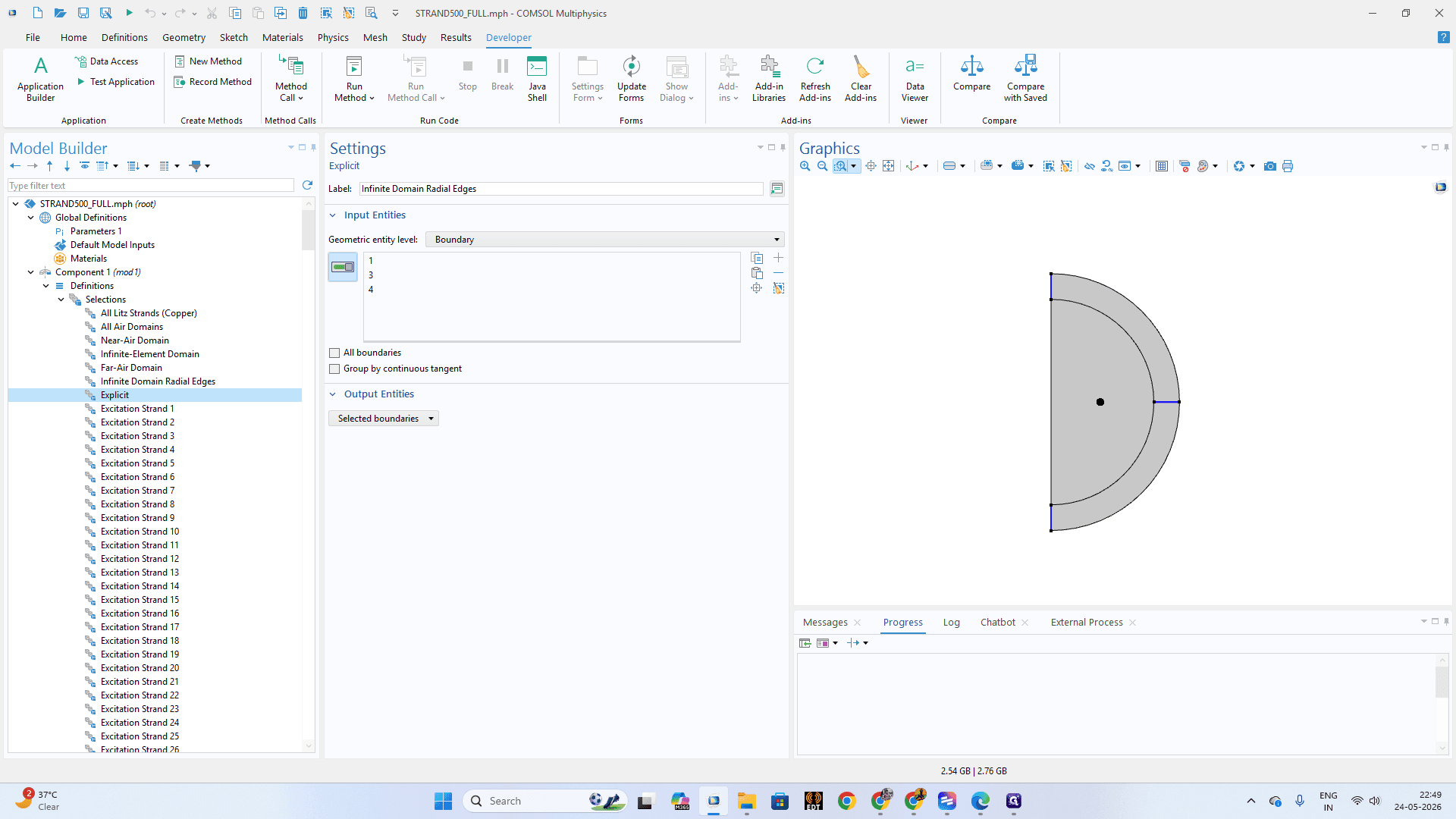
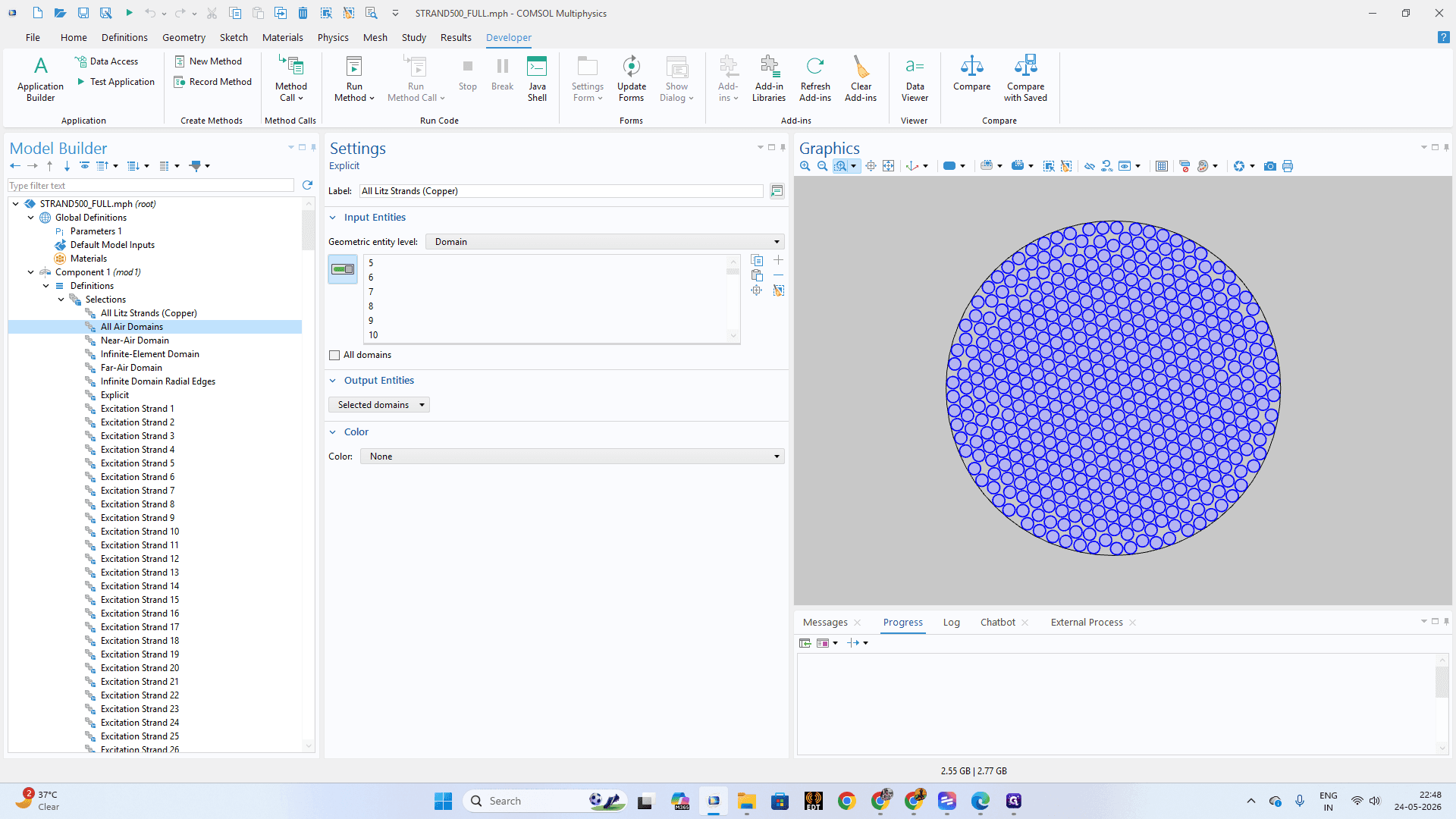
In the Model Builder under Component Definitions, select the Explicit node for All Litz Strands and ensure all relevant internal domains are highlighted.
Step #13: In the Model Builder under Component Definitions, select the Explicit node for All Litz Strands and ensure all relevant internal domains are highlighted.
14
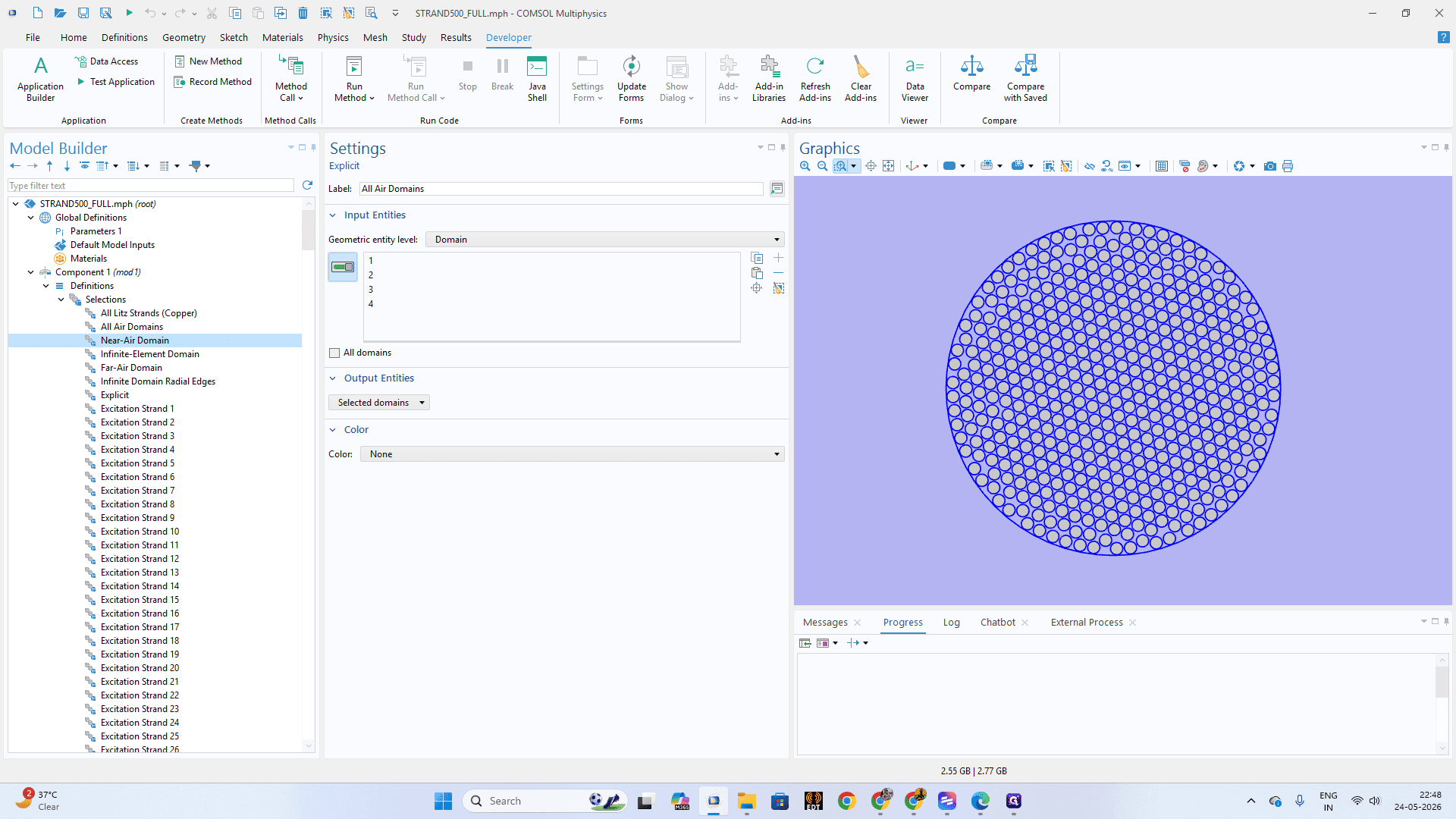
Click on Near-Air Domain to map the air buffer region immediately surrounding your strands.
Step #14: Click on Near-Air Domain to map the air buffer region immediately surrounding your strands.
15
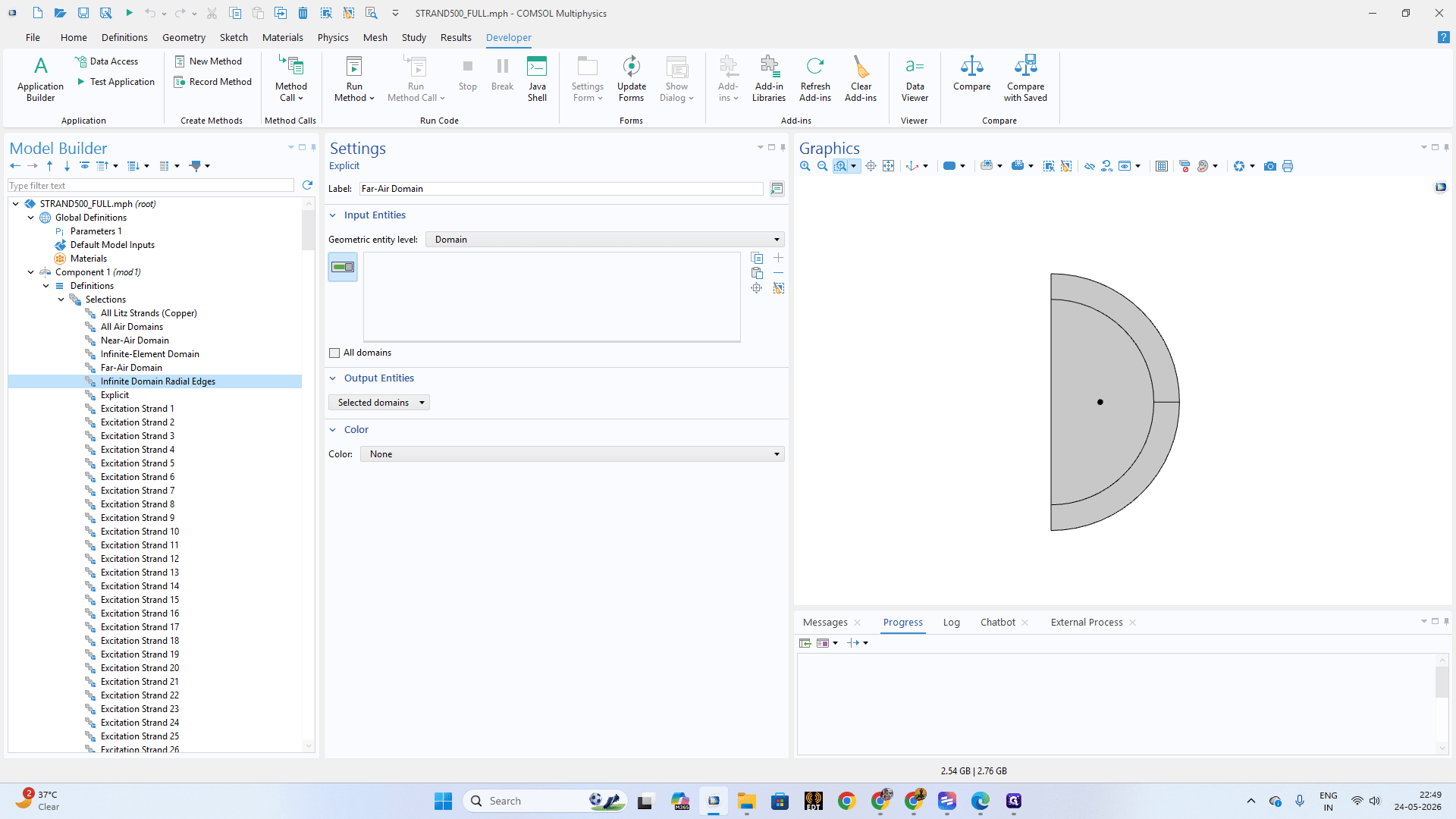
Select the Far-Air Domain node to map the wider bounding geometry.
Step #15: Select the Far-Air Domain node to map the wider bounding geometry.
16
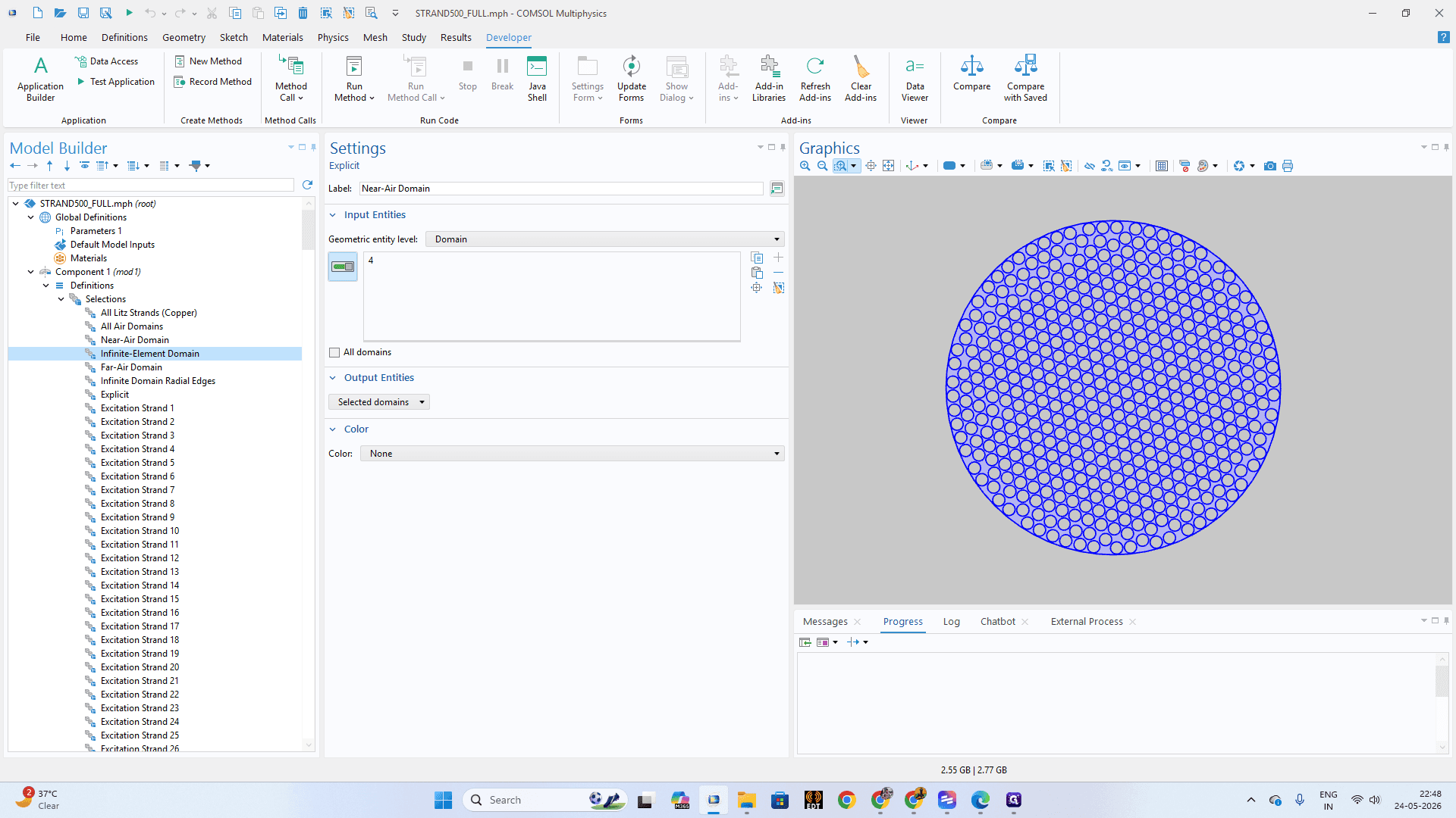
Click on the Infinite-Element Domain node to configure the outermost boundaries of your model for accurate electromagnetic falloff.
Step #16: Click on the Infinite-Element Domain node to configure the outermost boundaries of your model for accurate electromagnetic falloff.
17
Click on individual strands like Excitation Strand 1 through Excitation Strand 27 to ensure discrete domains are properly assigned to their standalone nodes.
Step #17: Click on individual strands like Excitation Strand 1 through Excitation Strand 27 to ensure discrete domains are properly assigned to their standalone nodes.
18
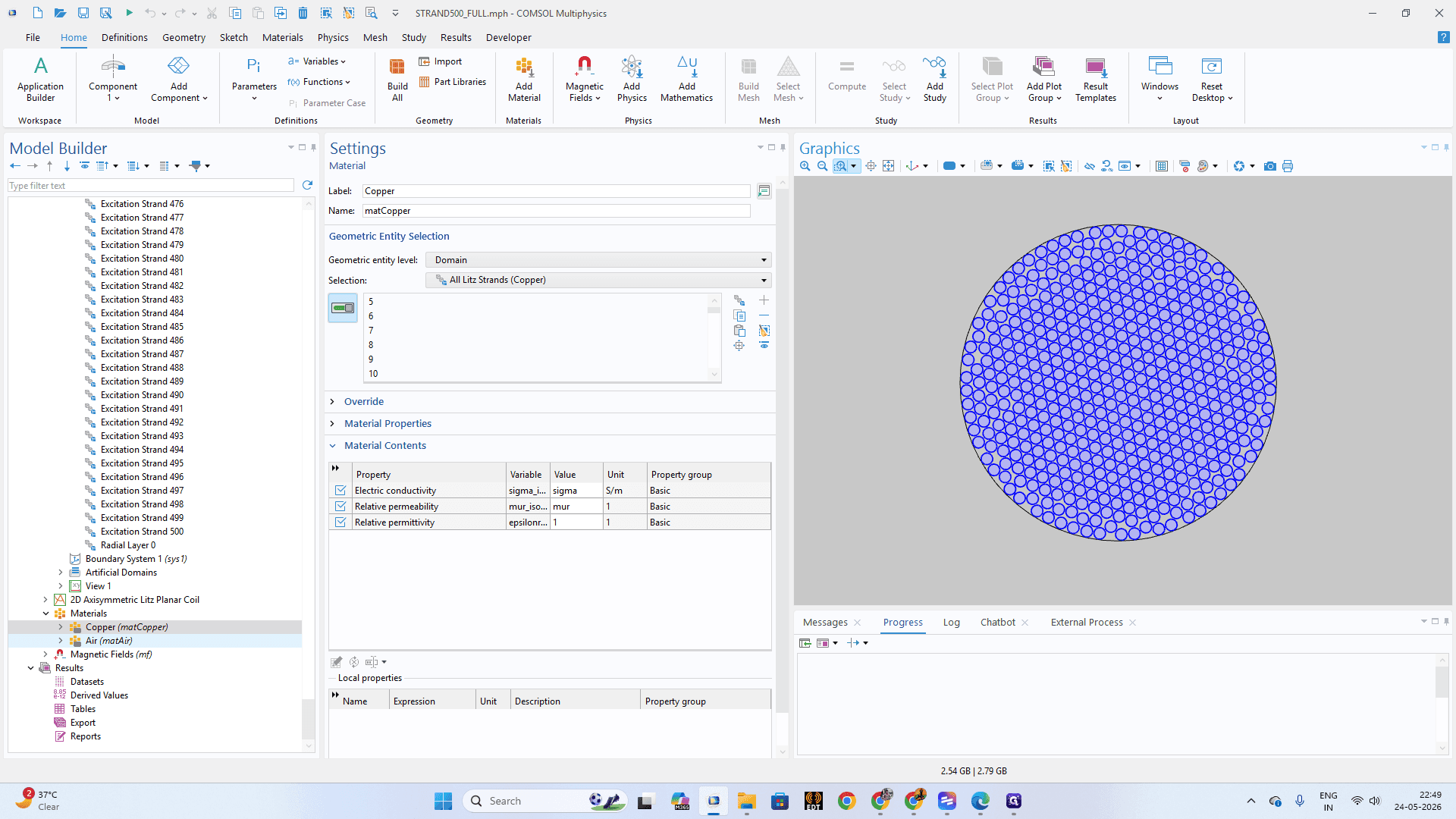
Under the Materials node, click on Copper (matCopper). In the Material Contents table, verify the target Electric conductivity is assigned to your Litz Strands selection.
Step #18: Under the Materials node, click on Copper (matCopper). In the Material Contents table, verify the target Electric conductivity is assigned to your Litz Strands selection.
19
Click on Air (matAir) and ensure the Relative permittivity is set to 1 for the surrounding domains.
Step #19: Click on Air (matAir) and ensure the Relative permittivity is set to 1 for the surrounding domains.

Configuring Magnetic Field Physics
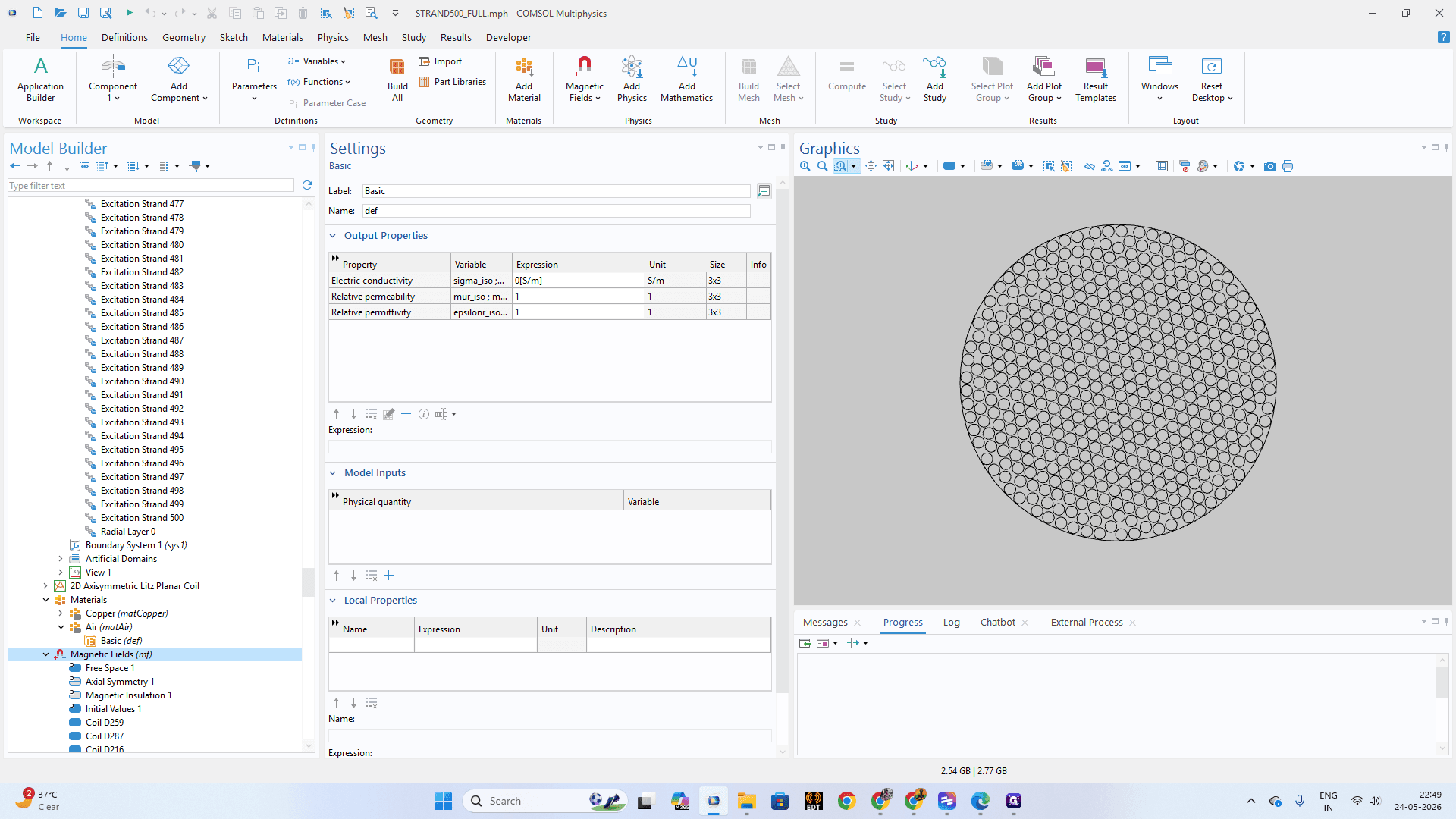
20
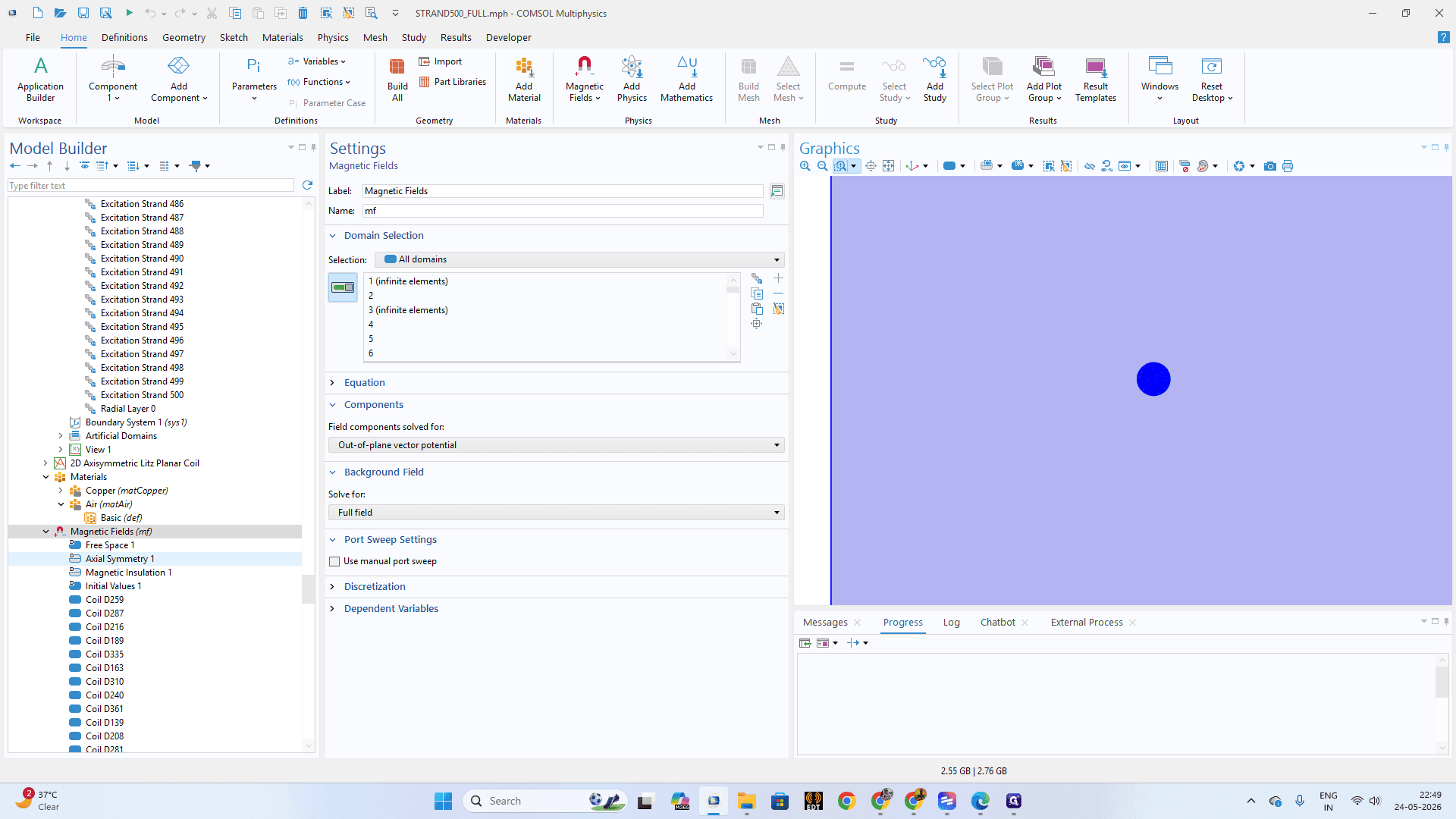
Click on the Magnetic Fields (mf) node in the Model Builder to access physics settings.
Step #20: Click on the Magnetic Fields (mf) node in the Model Builder to access physics settings.
21
Select Axial Symmetry 1 to enforce rotational symmetry behavior on the 2D cross-section.
Step #21: Select Axial Symmetry 1 to enforce rotational symmetry behavior on the 2D cross-section.
22
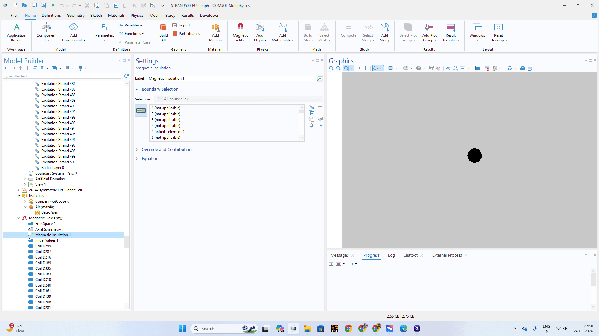
Check the Magnetic Insulation 1 boundary conditions to ensure external boundary boundaries constrain the magnetic field correctly.
Step #22: Check the Magnetic Insulation 1 boundary conditions to ensure external boundary boundaries constrain the magnetic field correctly.
23
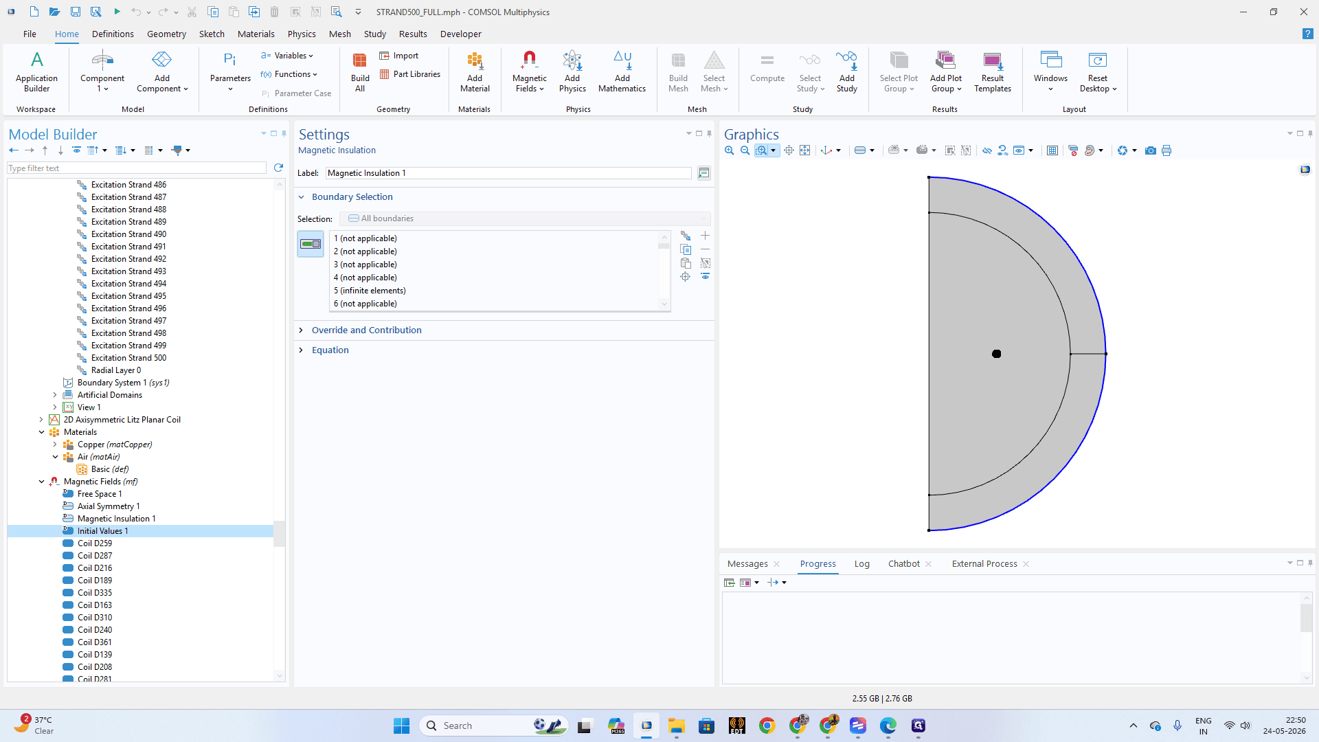
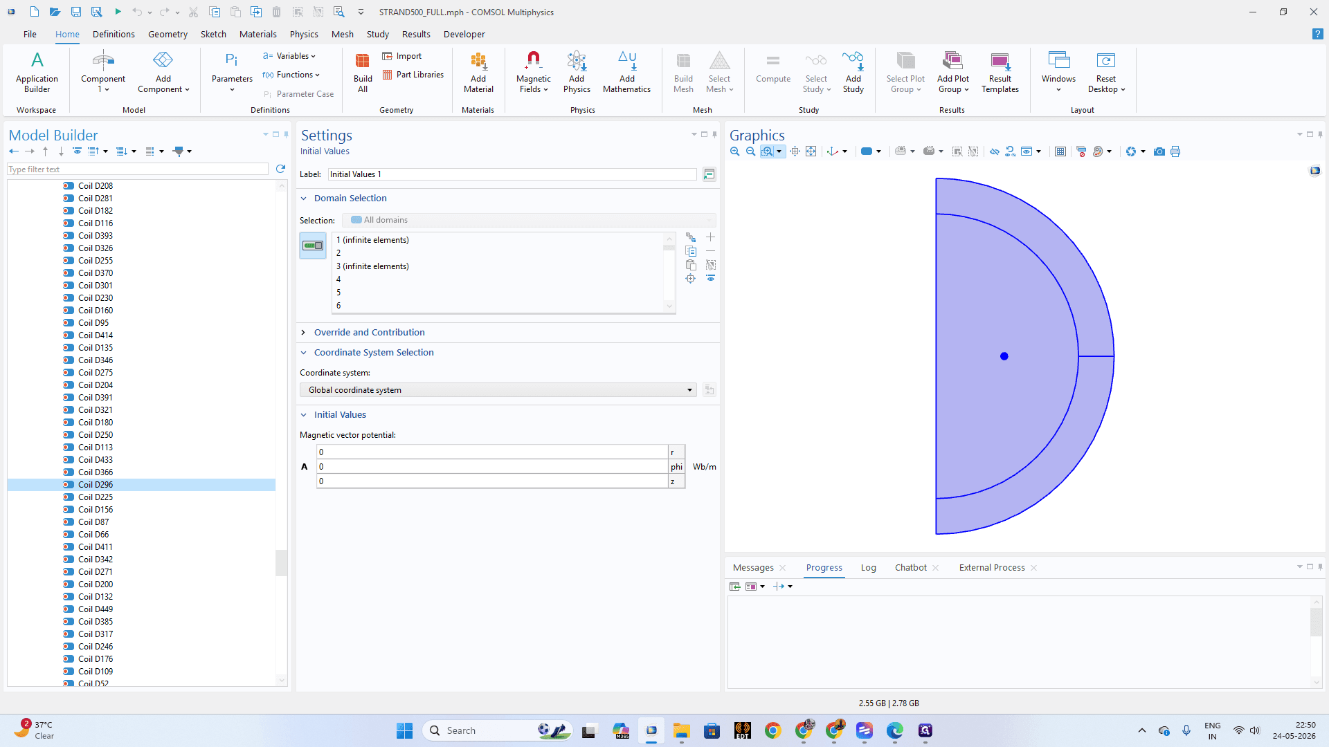
Click Initial Values 1 to verify the baseline magnetic potential starts at zero.
Step #23: Click Initial Values 1 to verify the baseline magnetic potential starts at zero.
24
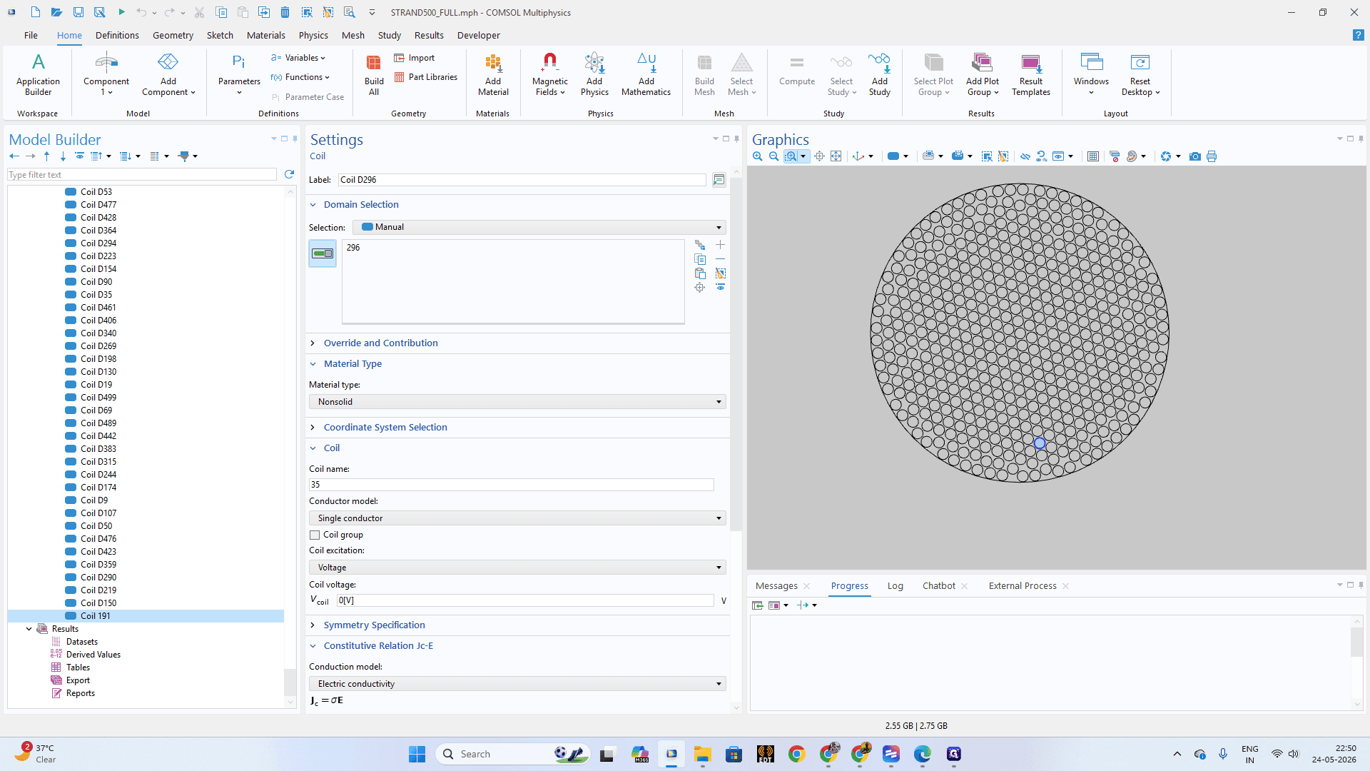
Under the Magnetic Fields branch, navigate to individual coil sub-nodes (e.g., Coil D296).
Step #24: Under the Magnetic Fields branch, navigate to individual coil sub-nodes (e.g., Coil D296).
25
Click on Coil 191 (and proceed down the list). In the Settings panel, verify the assigned domains, excitation voltage, and constitutive relations match your physical specifications.
Step #25: Click on Coil 191 (and proceed down the list). In the Settings panel, verify the assigned domains, excitation voltage, and constitutive relations match your physical specifications.

FAQ

Q: Why use a custom Java method for mesh sizing instead of the standard mesh node?

A: For highly complex, repetitive structures like Litz wire bundles, writing a custom Application Builder method allows you to iterate through hundreds of individual strands programmatically. This ensures perfectly uniform mesh parameterization without hours of manual data entry.

Q: Do I need to manually map every excitation strand to its own coil node?

A: Yes. To accurately simulate skin and proximity effects in a Litz planar coil, each strand must be treated as an independent geometric domain and configured with discrete excitation properties.

Glossary

Term

Definition

Litz Planar Coil

A specialized electromagnetic coil wound from multi-strand wire designed to reduce skin effect and proximity effect losses at high frequencies.

Application Builder

A workspace within COMSOL Multiphysics used to build custom user interfaces or write Java methods to automate complex modeling tasks.

Explicit Selection

A designated grouping of geometric entities (domains, boundaries, edges, or points) manually selected to make assigning materials or physics easier.