
How to Create a Structural Framing Plan in AutoCAD LT
Learn how to set up a second-floor framing plan using Xrefs, configure clipping boundaries, and draft structural joists and headers in AutoCAD LT.
This guide outlines how to set up a structural framing plan in AutoCAD LT by utilizing architectural background external references (Xrefs). You will learn to properly overlay background files, configure clipping boundaries, place scaled structural annotations (like wood joists and headers), and duplicate the layout for additional foundation plans.
This workflow is designed for structural drafters and engineers detailing framing plans from architectural models. It is typically performed during the initial schematic layout phase of a structural drafting project.
Configuring Background Xrefs
Begin by bringing the architectural CAD files into your engineering drawing.
xref and press Enter to open the External References palette.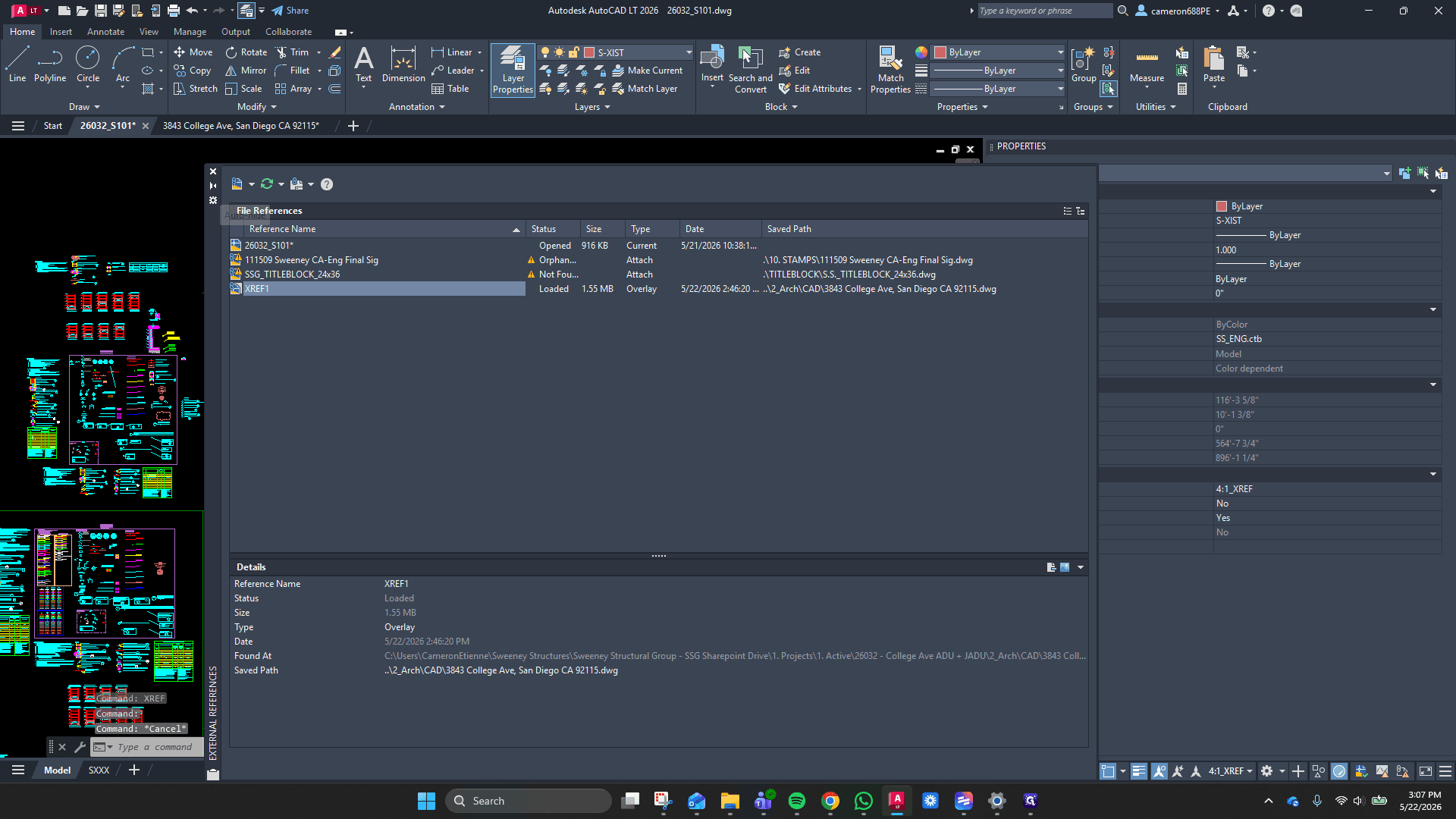
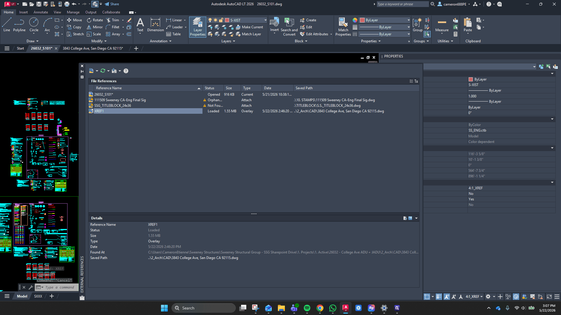
To focus solely on the first-floor perimeter walls that interact with the second-floor framing, you will need to clip out unnecessary areas.
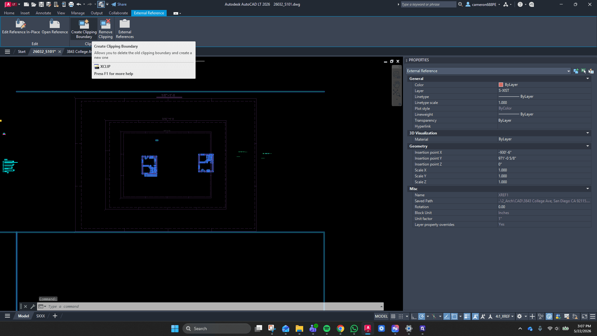
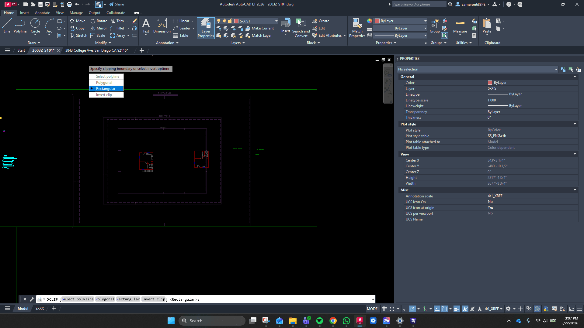
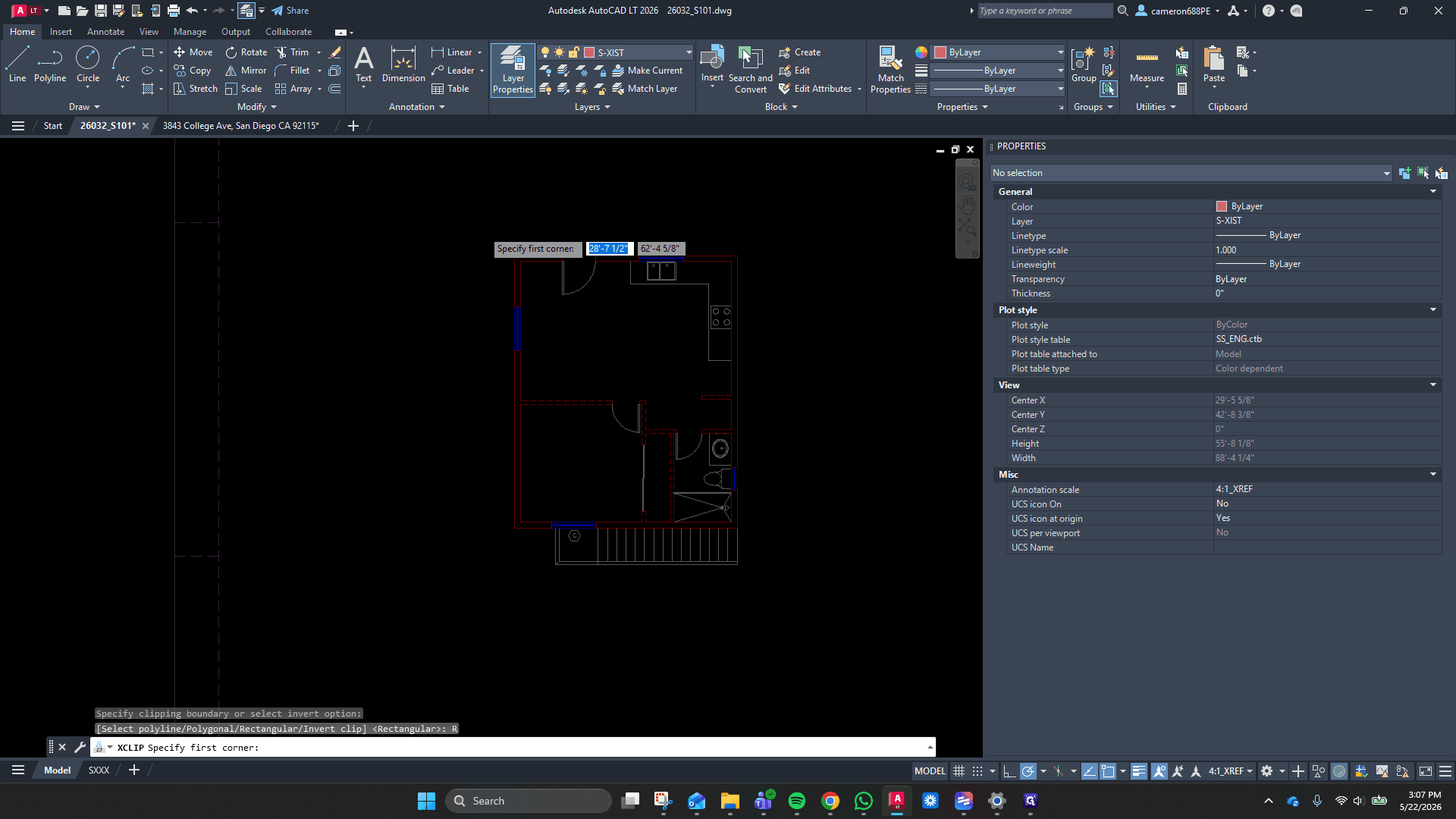
To clean up the drawing layout, hide the boundary line so it doesn't plot.
XCLIPFRAME and press Enter.0 and press Enter to make the clipping frame invisible.Placing and Scaling Structural Annotations
Ensure your view properly accommodates the structural blocks and text needed for the plan.
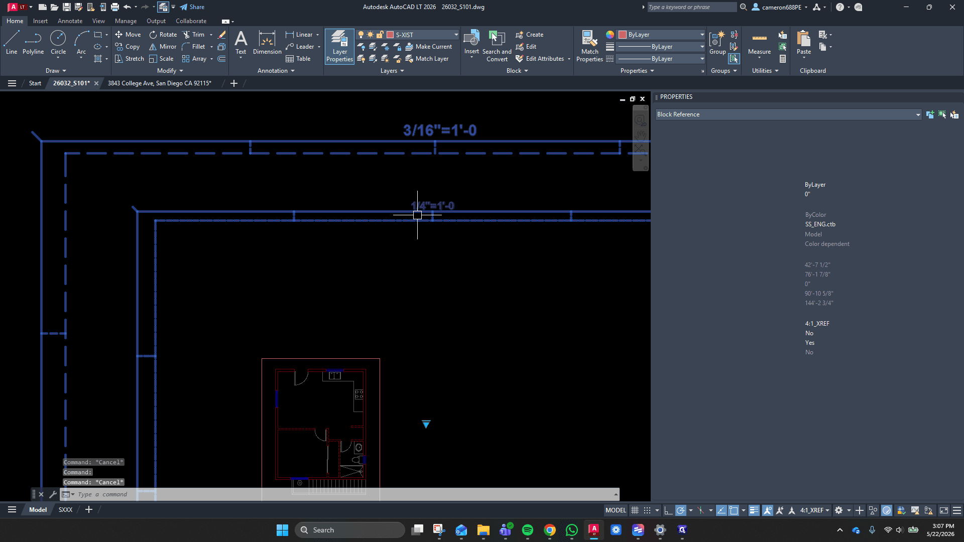
Now, define the specific joists needed for the decking.
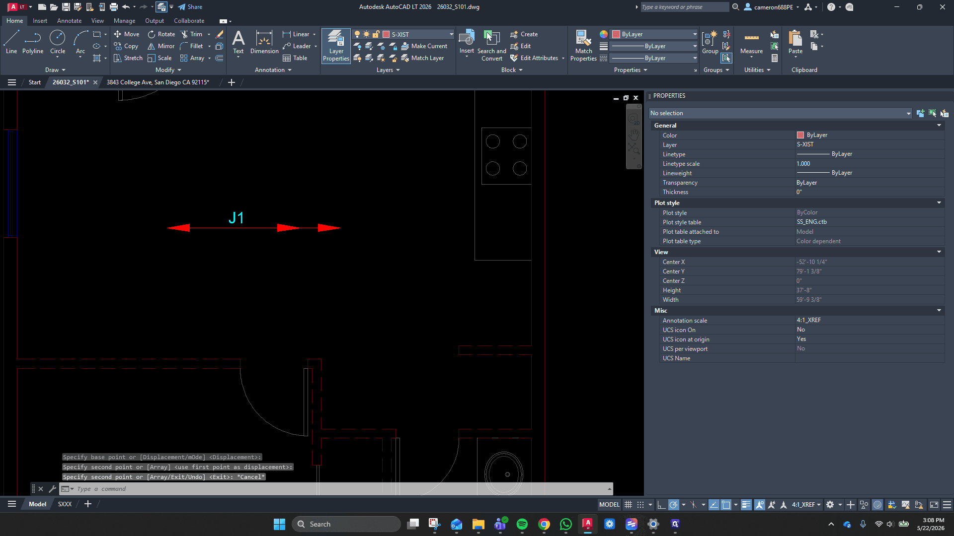
J212, and press Tab/Enter to apply the change.Drafting Headers Over Openings
You must note the location of structural headers across applicable window and door openings.
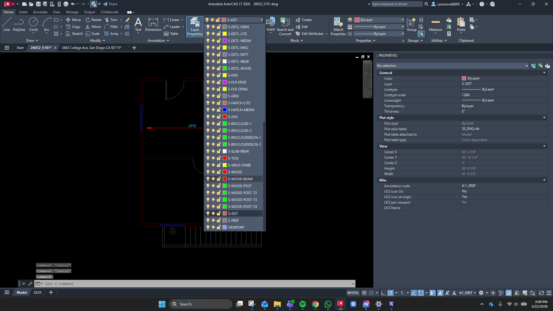
L and press Enter to initiate the Line command.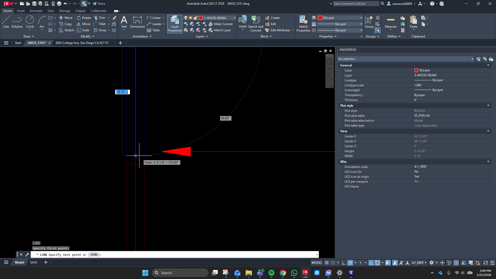
Next, assign text callouts to your drawn header lines based on your beam schedule.
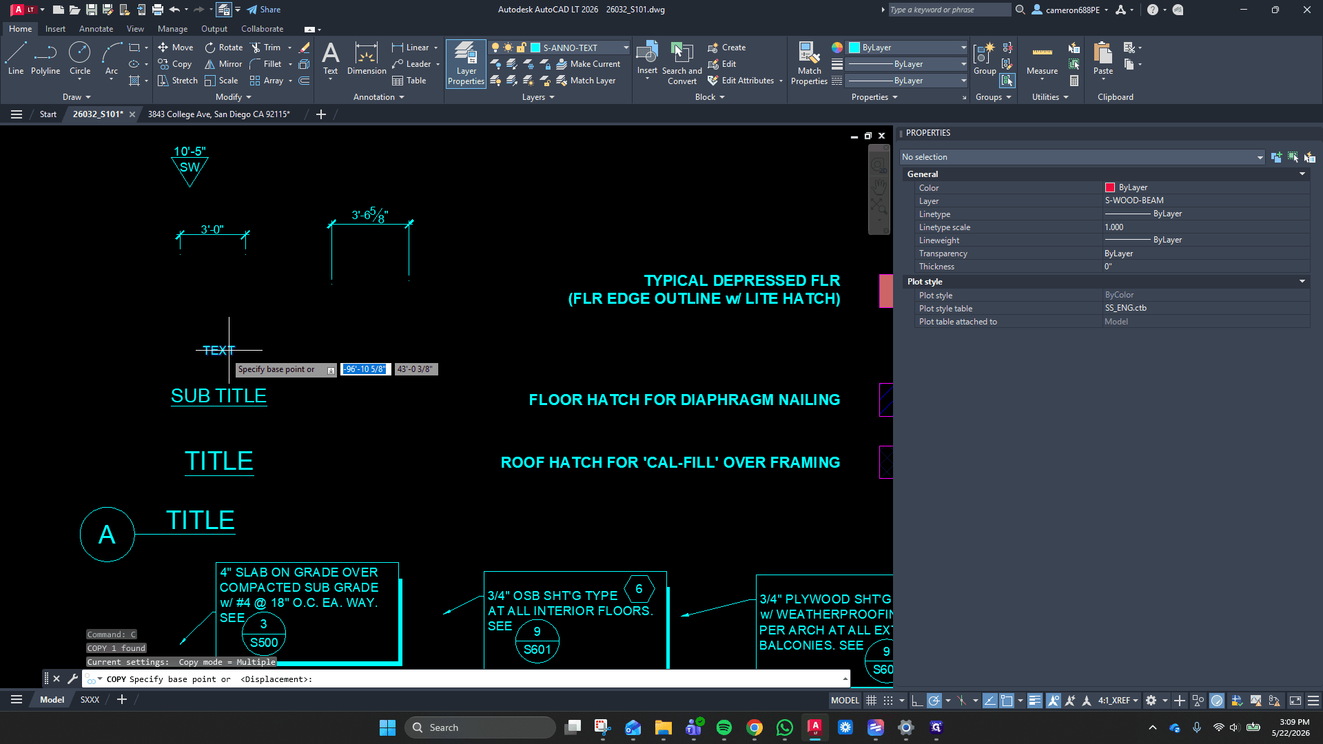
HDR into the text field to label a typical header.M to move the text directly adjacent to your newly drafted line.C and select both the HDR text and the line to copy the group.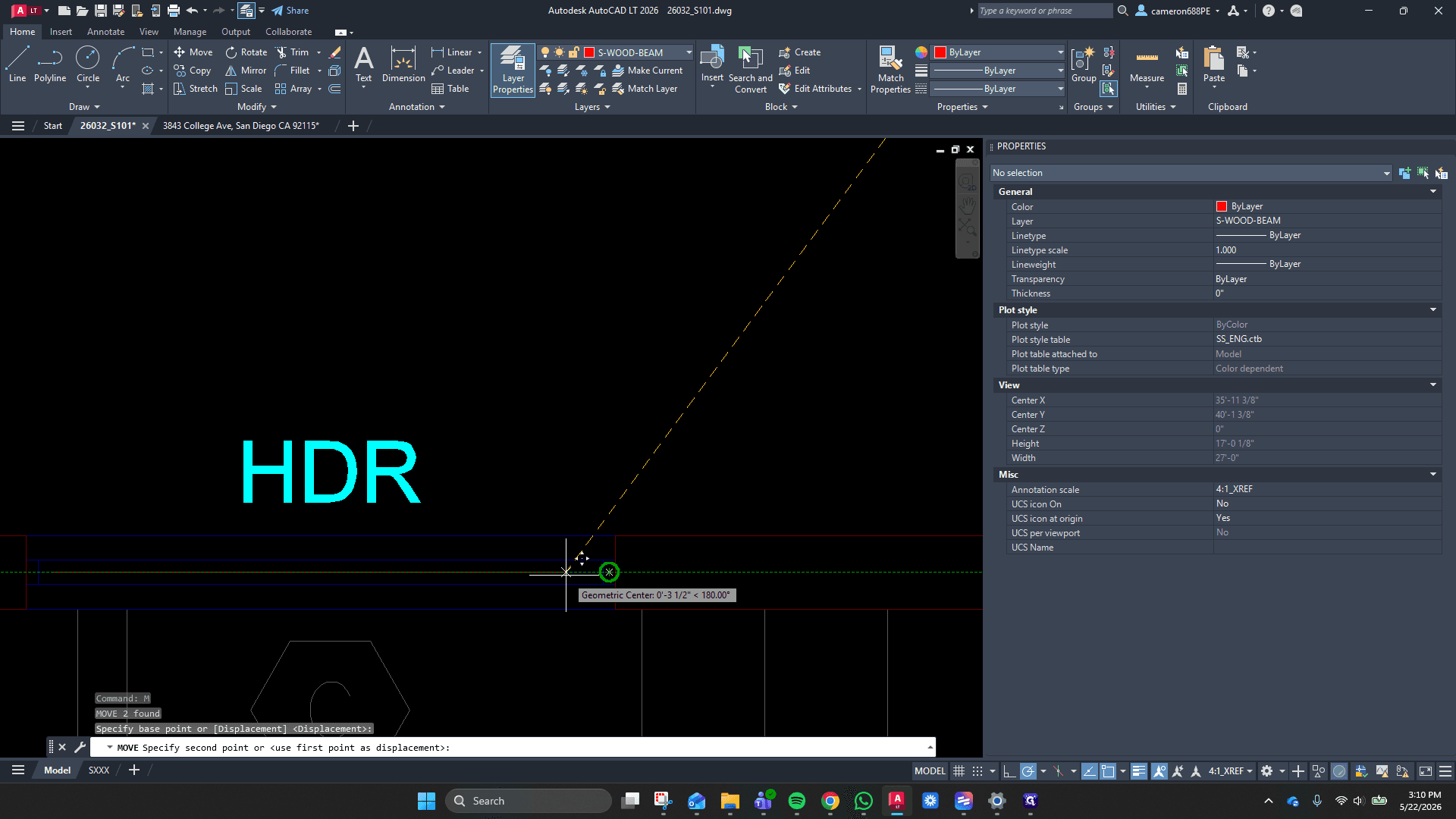
Preparing Additional Plans
Once the second-floor framing plan is schematically laid out, you can duplicate it to serve as the baseline for the foundation plan.
C to copy the main title block text (e.g., "SECOND FLOOR FRAMING PLAN").C to copy the entire architectural background Xref into the open space next to your current drawing, providing a fresh footprint for the foundation layout.FAQ
Q: Why do we set the architectural background to "Overlay" instead of "Attach"?
A: Setting Xrefs to "Overlay" is standard file hygiene. It ensures that if the current drawing is ever referenced into a third drawing, the background architectural file doesn't pull through, thereby preventing file bloating and circular references.
Q: Do I need to place headers over every door in the building?
A: No. Headers are structural elements and should only be placed in structural or load-bearing walls. Interior, non-structural openings do not require header annotations on the framing plan.
Q: When can I use the standard "HDR" callout?
A: In this workflow, the typical "HDR" schedule callout can safely cover opening spans up to 10 feet long.
Glossary
Term | Definition |
|---|---|
Xref | External Reference; a file linked to the current AutoCAD drawing rather than being permanently embedded. |
XCLIP | An AutoCAD command used to hide parts of a block or external reference outside a specified rectangular or polygonal boundary. |
Header | A horizontal structural beam positioned over door or window openings to distribute weight away from the gap. |