How to Export Orthomosaics from PIX and Import into Global Mapper and CAD
Learn step-by-step how to export an ortho from PIX, import it into Global Mapper, and export it for use in CAD. This guide covers correct projection settings, file formats, and tips for seamless integration.
In this guide, we'll learn how to export an orthomosaic image from PIX, import it into Global Mapper, and then export it with the correct settings for use in other applications. We will also cover how to ensure the exported files have the right projection and format for compatibility with CAD and TBC. This process helps maintain accurate geospatial data and smooth workflow between software.
Let's get started
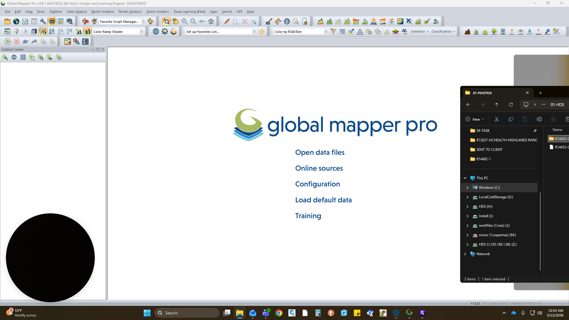
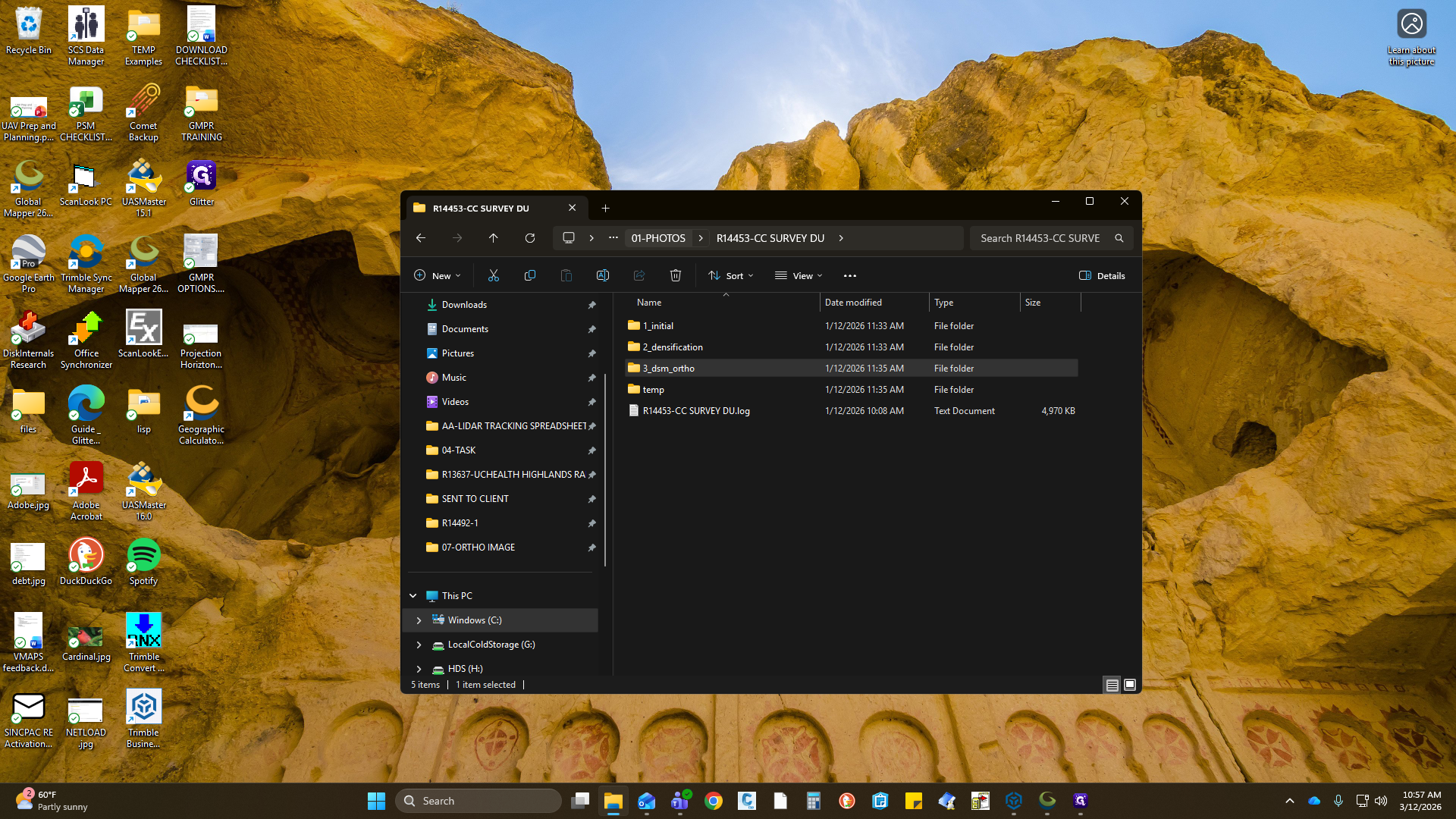
"" Today, we will discuss how to export an ortho from PIX, import it into Global Mapper, and export it using the correct procedures. I have Global Mapper open, and I am going to grab my raw orthomosaic from my PIX folder.
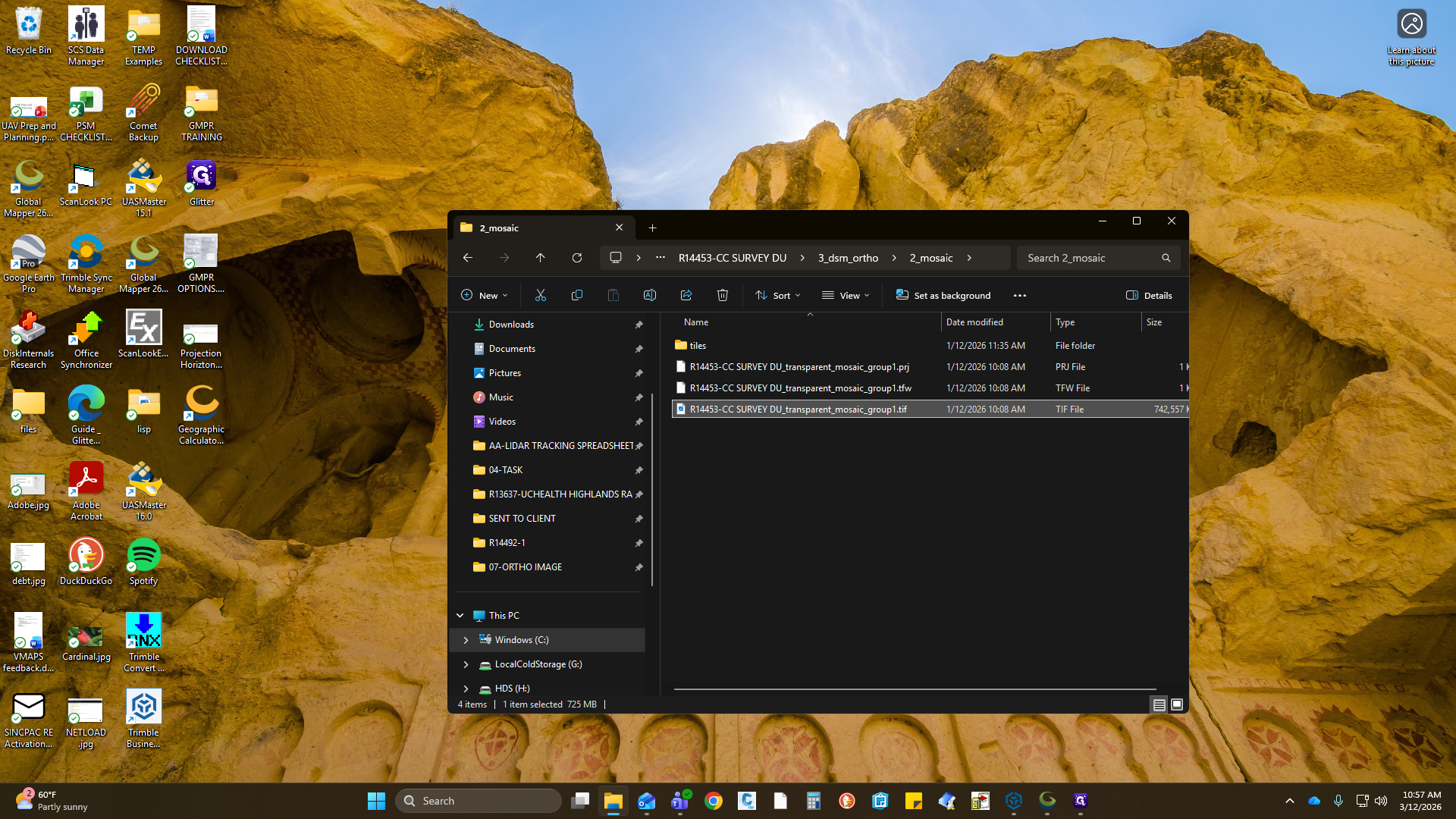
If you're familiar with PIX, under DSM Ortho, Mosaic, Tiles, there is a TIFF.


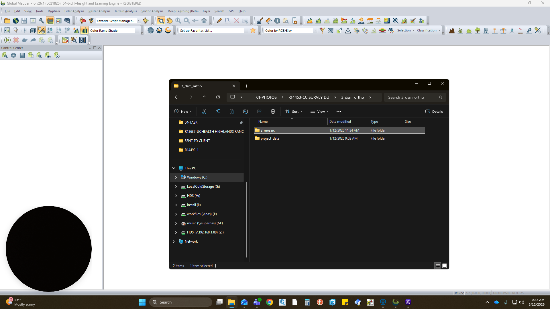


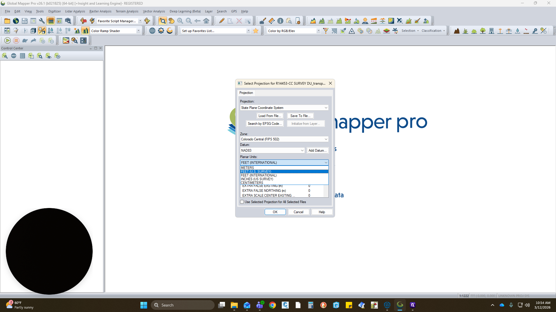
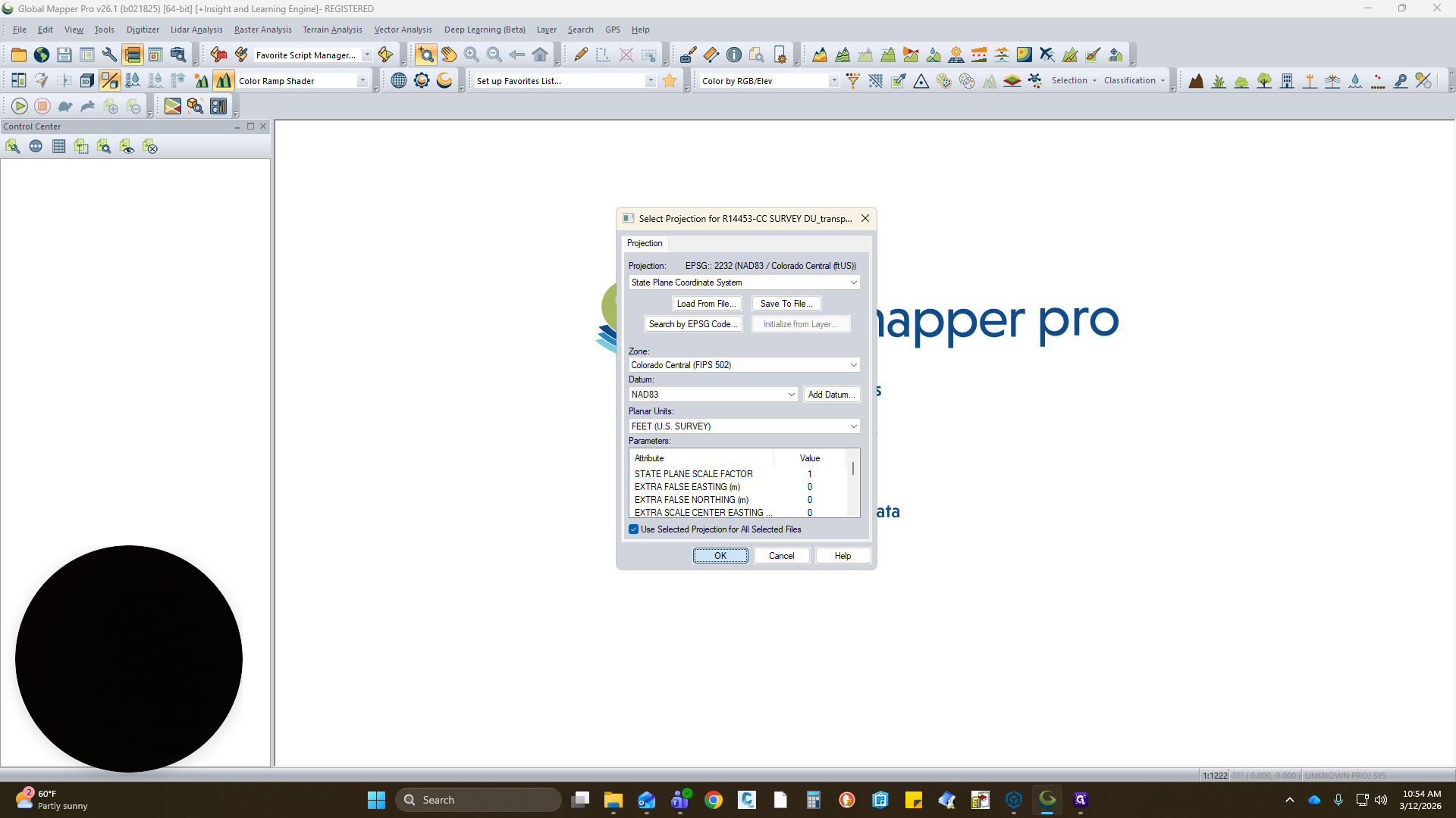
Load it in. This project is in Colorado Central, using State Plane, Colorado Central.
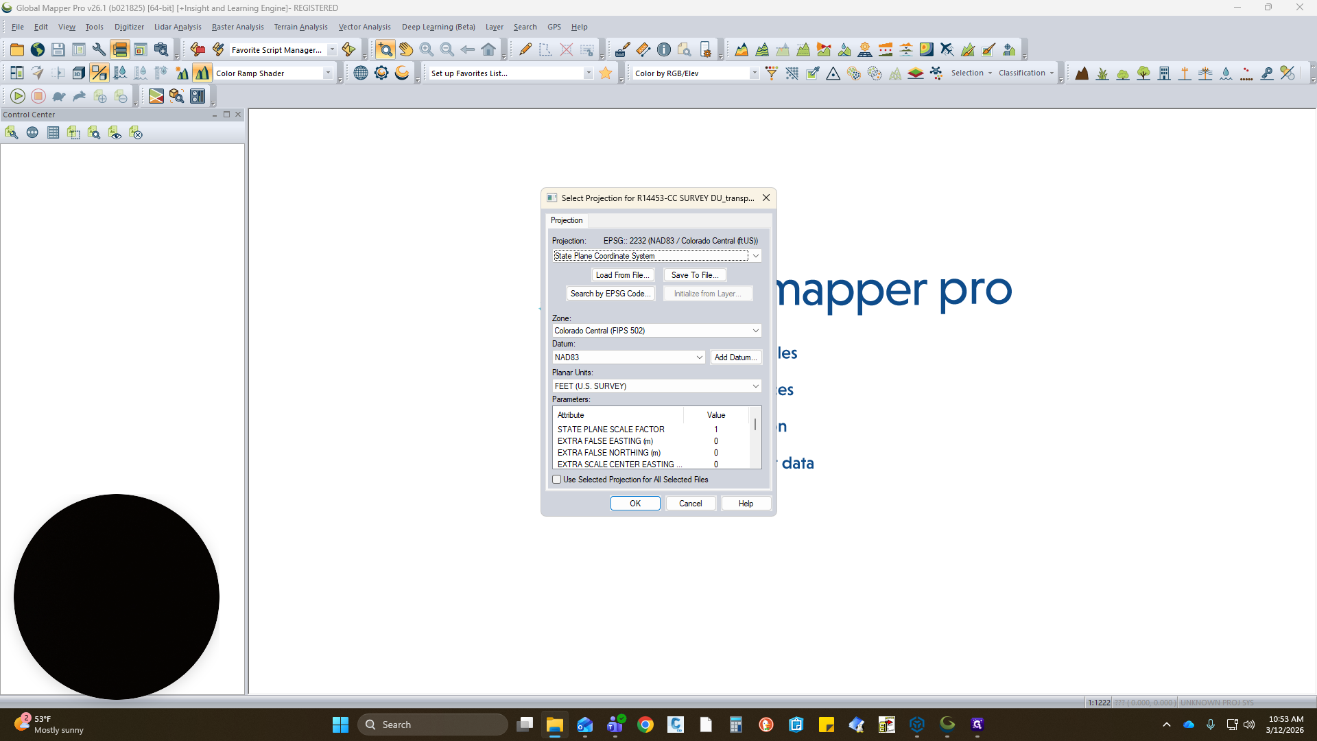

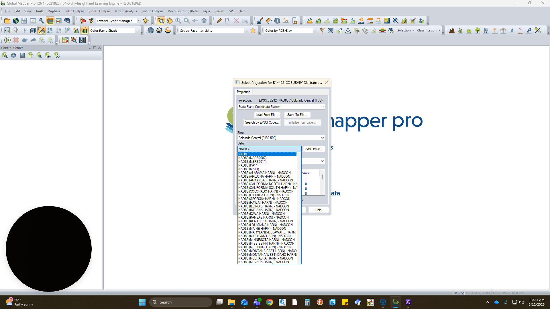
It's important that we use NAD 83. This was becoming an issue with CAD, where it was translating using the 2011 version.
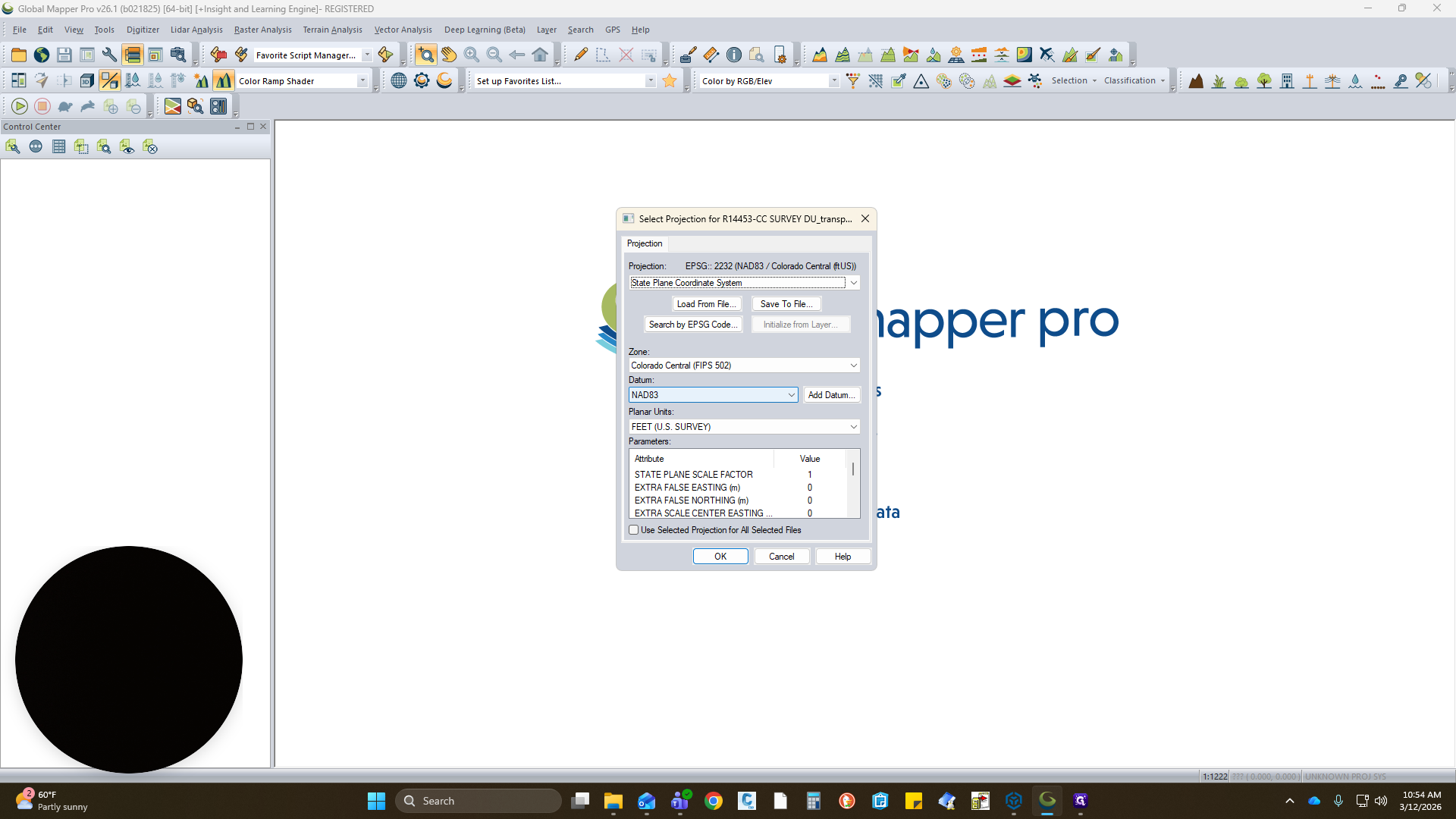

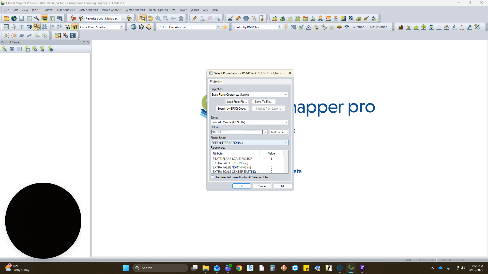
Select NAD 83, US Survey Foot, then click OK.

Here is your image. Just to the left, you can highlight this or right-click and select if you want.
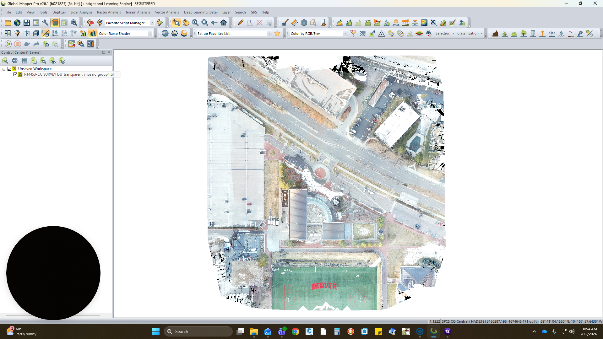

I have it highlighted.
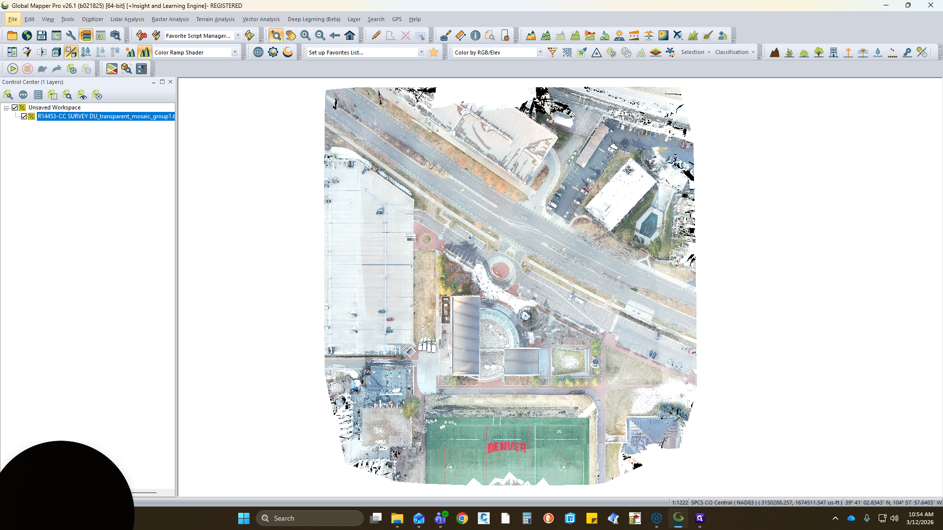
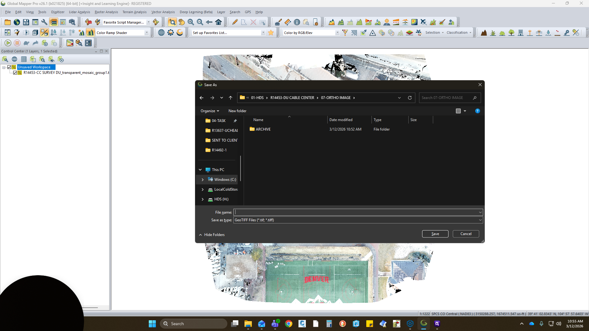
Select File, then Export, and choose Raster Image Format.
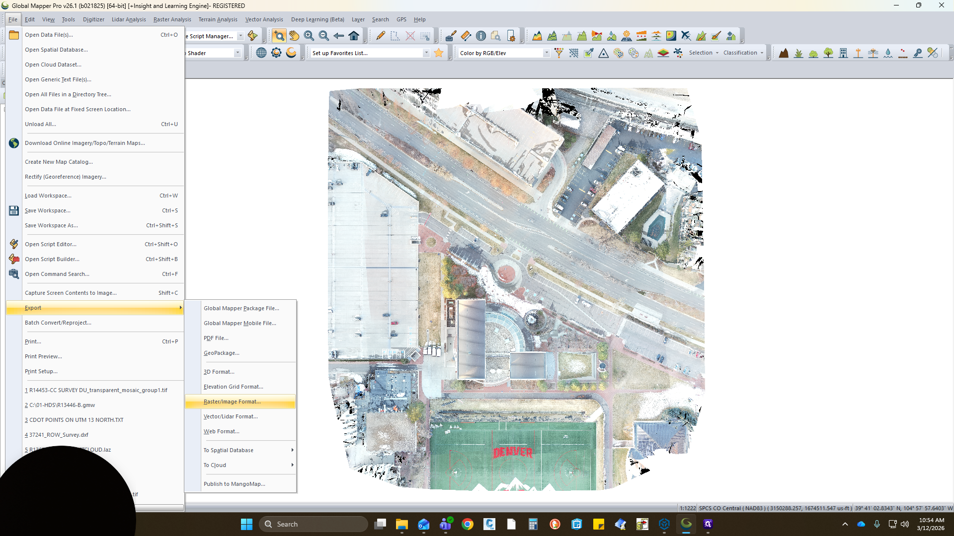
It should automatically prompt you with a GeoTIFF file.
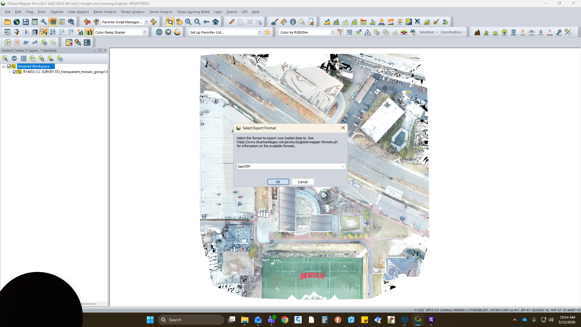
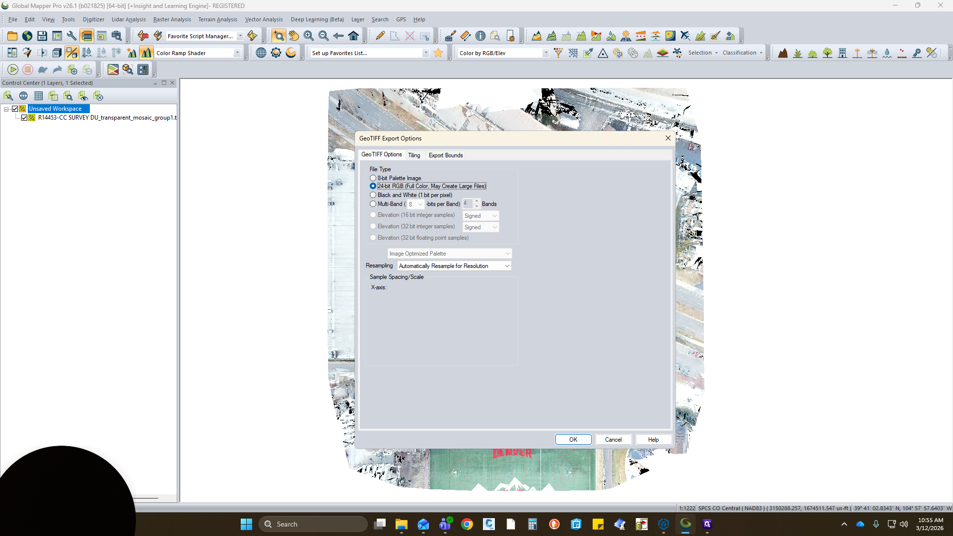
Click OK. Here are some of the updated attributes we want to select.
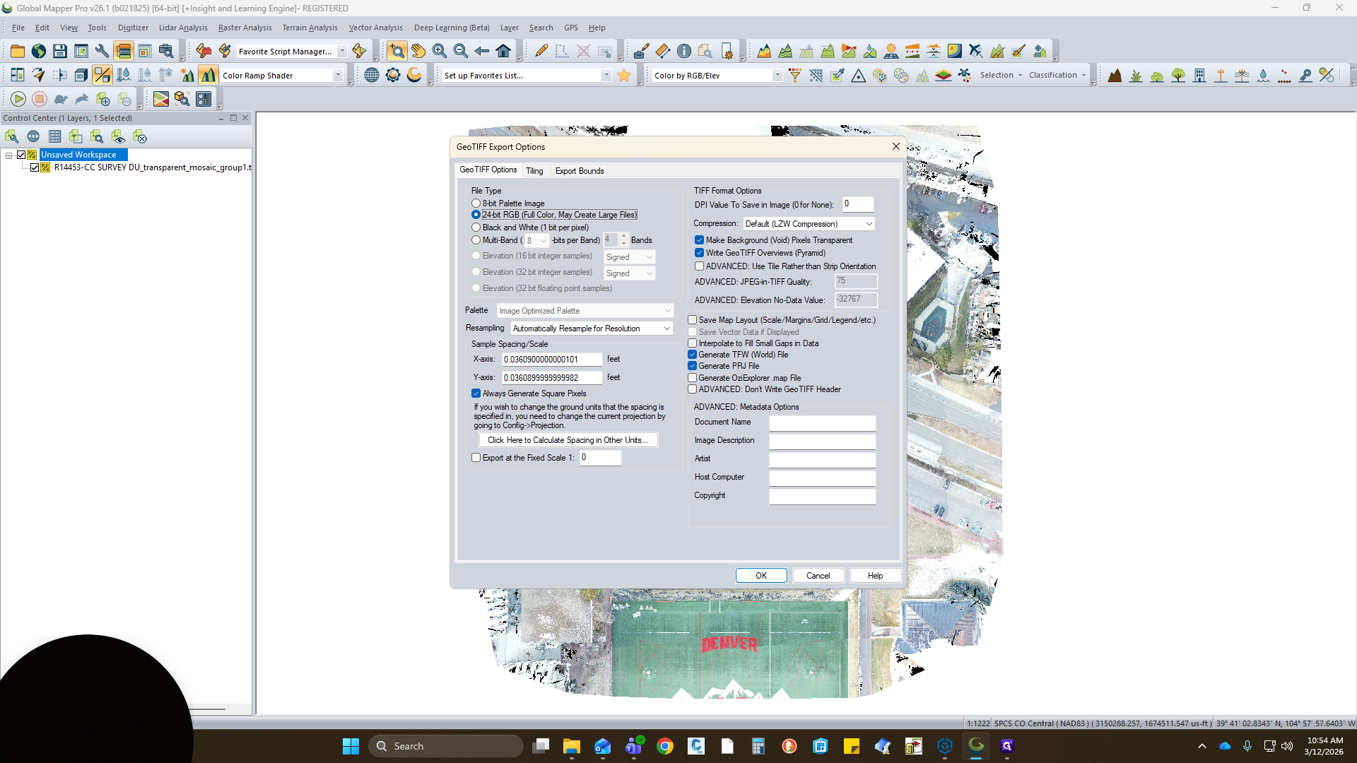
We do not want 8-bit; we want 24-bit RGB. CAD works with this a lot better. You can turn this on or off. It removes the white background at times.
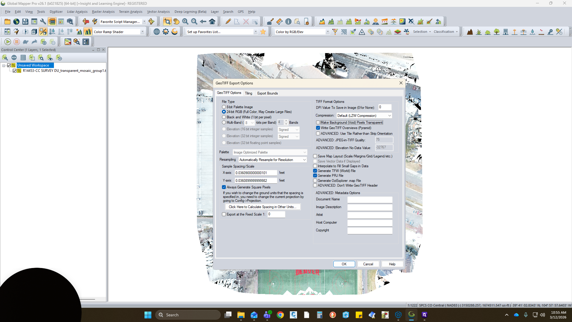
Make sure you have both Generate TFW World File and Generate Projection File selected. LAC compression is fine.

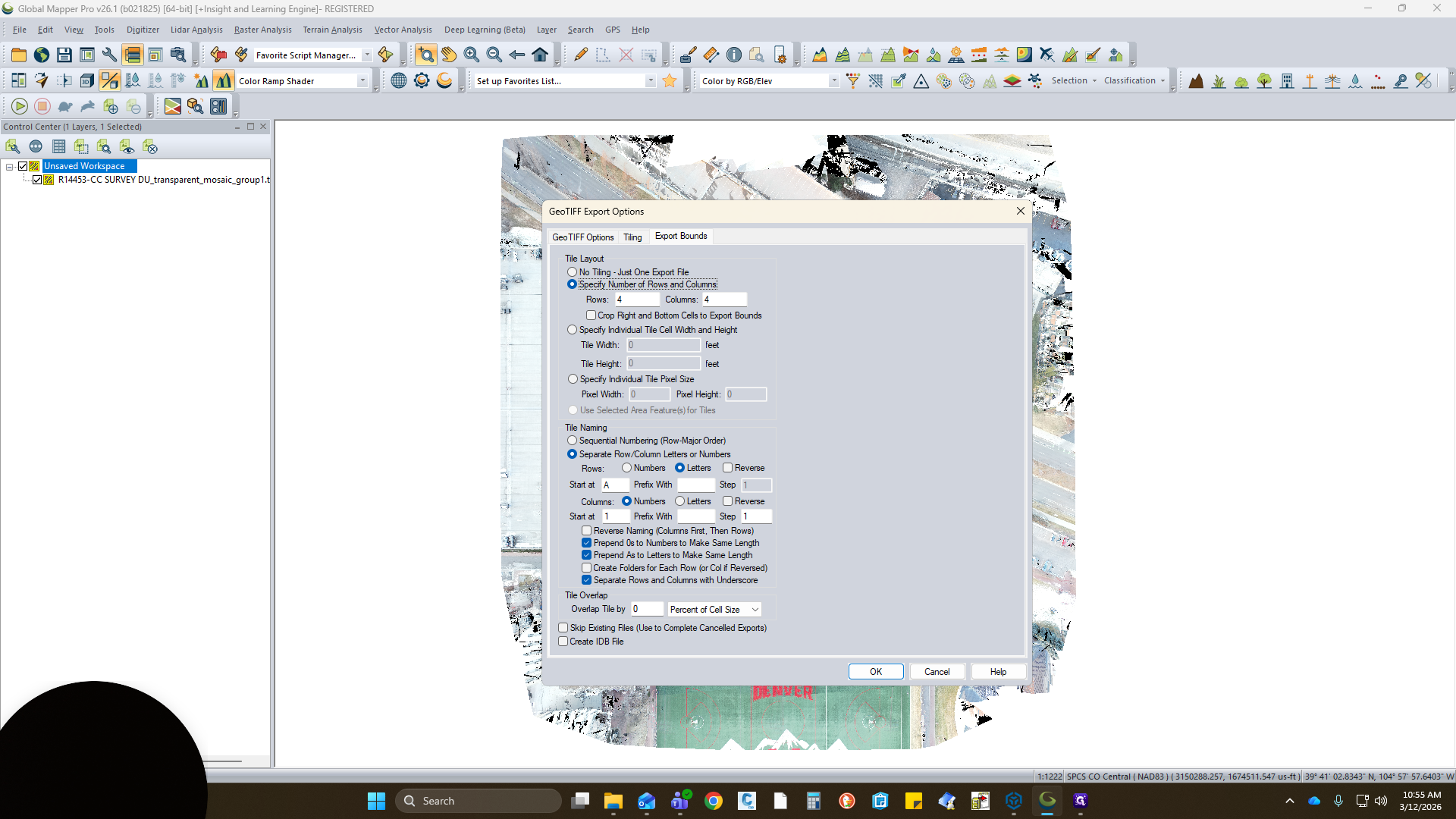
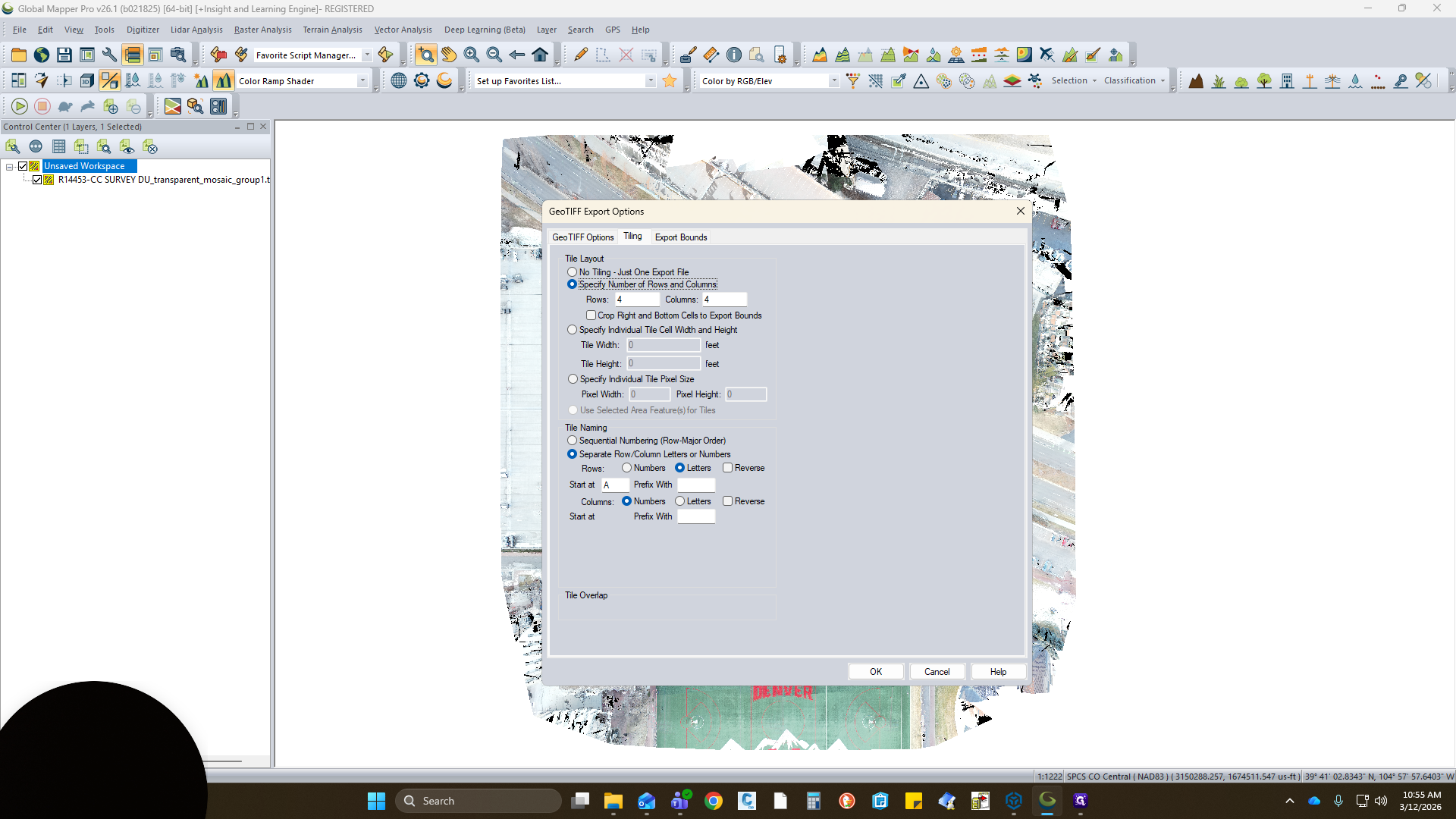
If you have a larger image, use the tiling option. You can select the number of rows and columns. Everything else should already be selected.

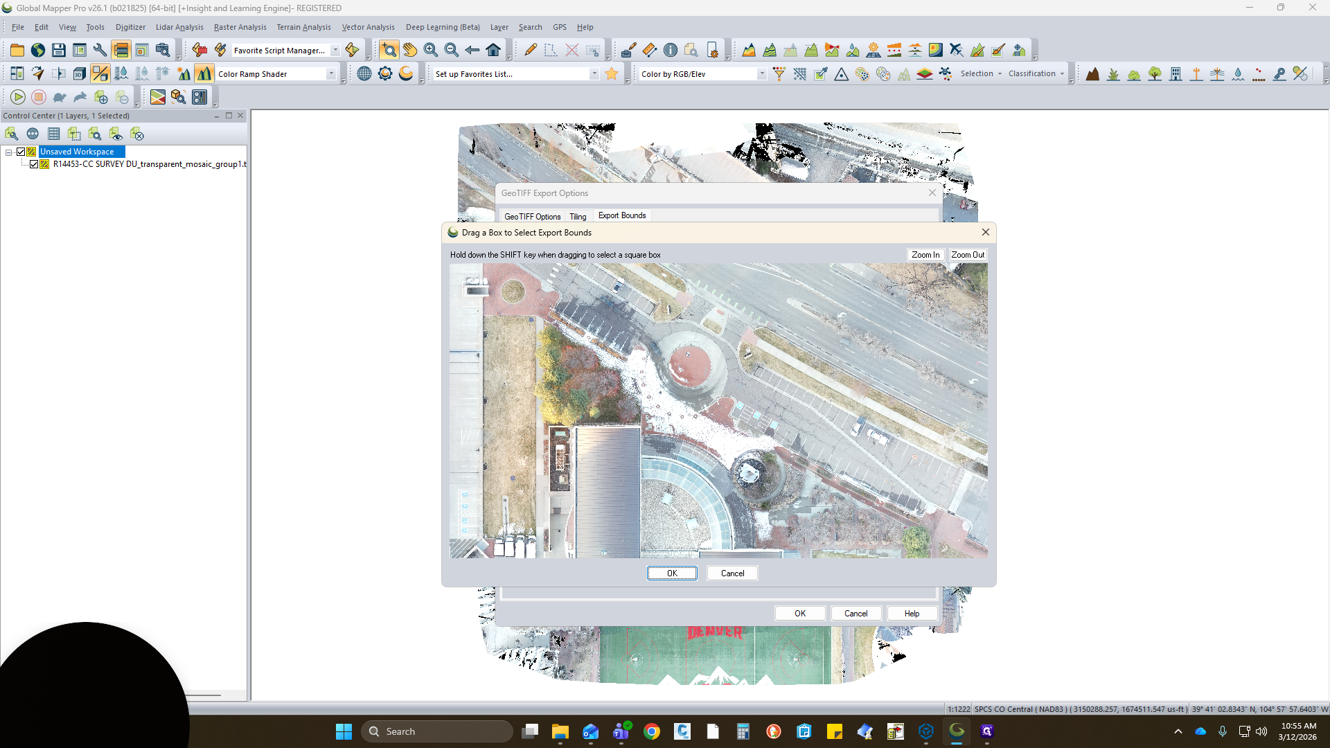
If you need a specific area, you can draw a box.

I will export the full version and click OK.


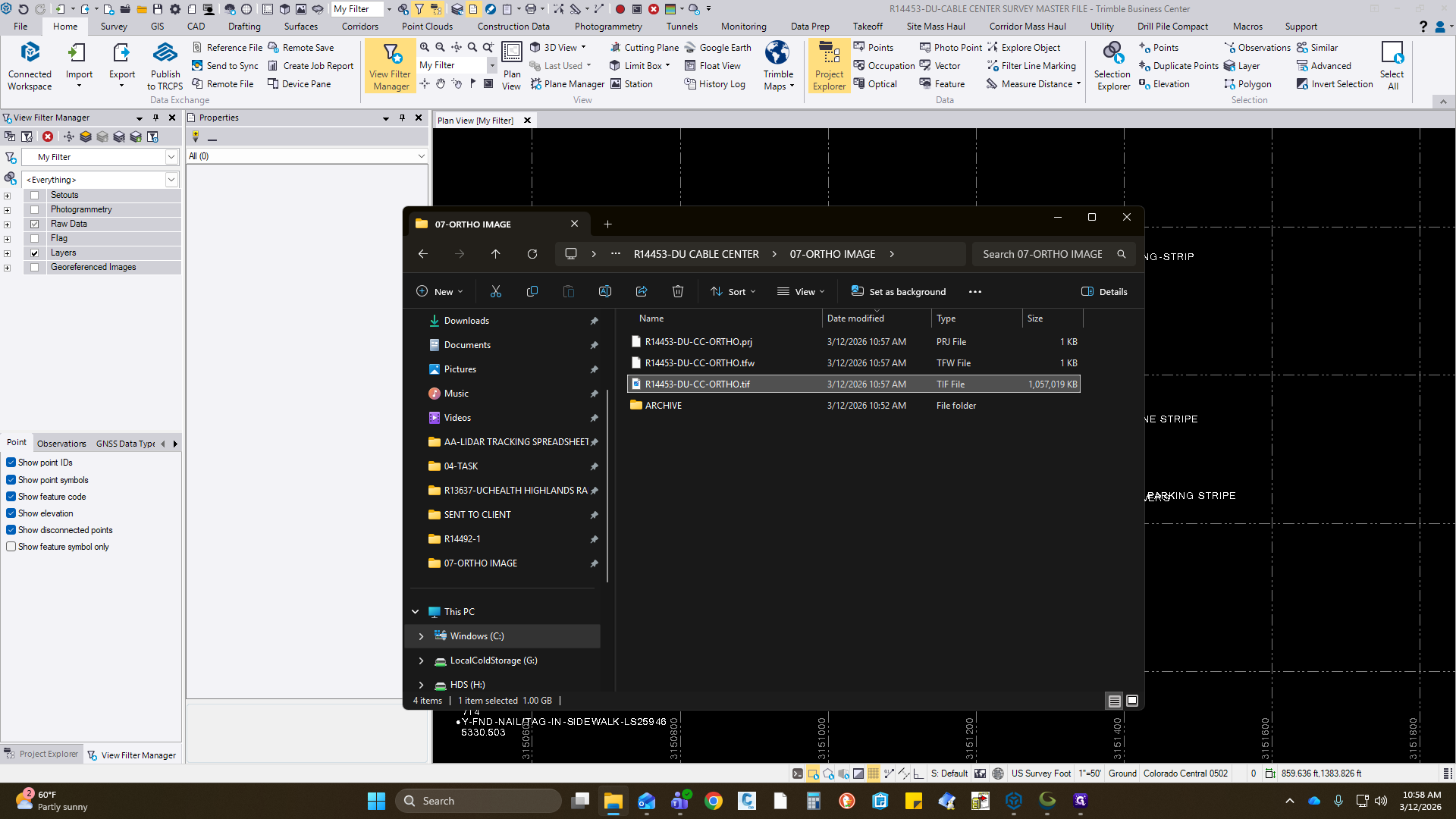
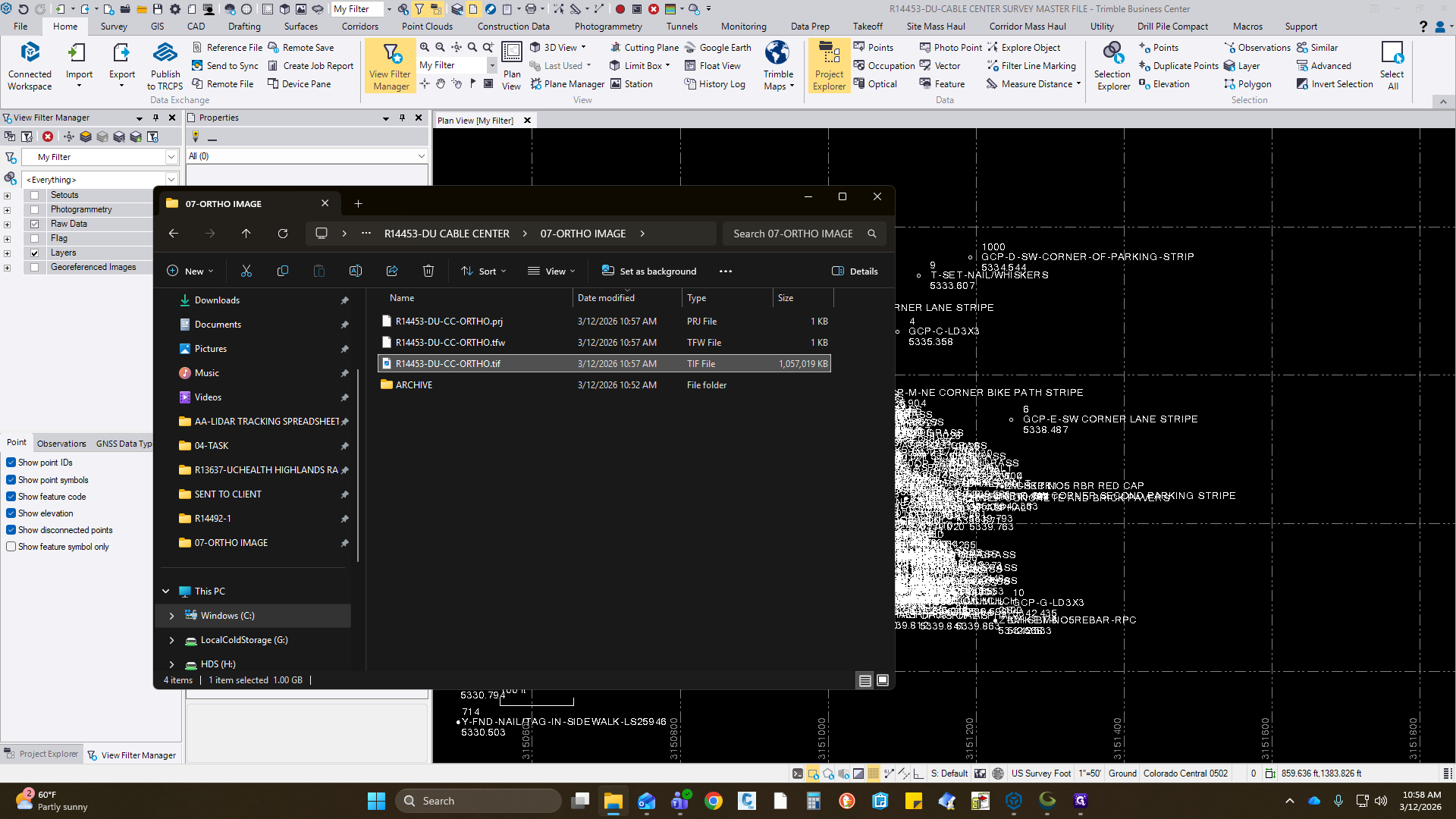
Inside the directory I saved, I will go to OrthoImage and name it.


Click Save and wait for the export to finish.
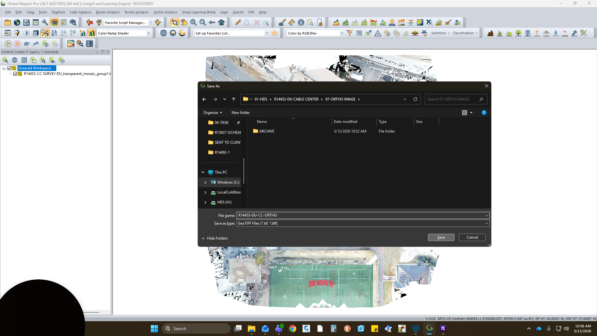
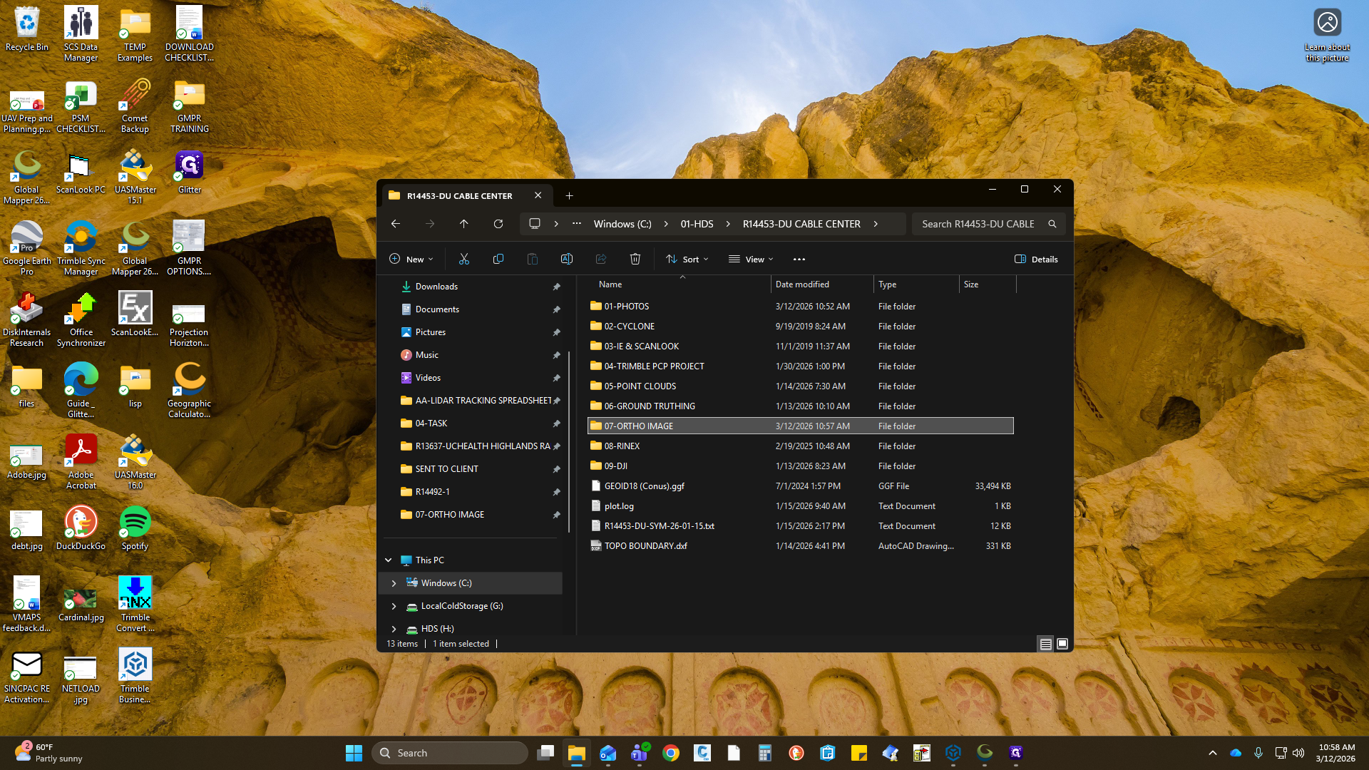
Upon its export... This box will disappear, and we can find the ortho in the directory. Nothing else changes. Minimize that. Go to my main folder.
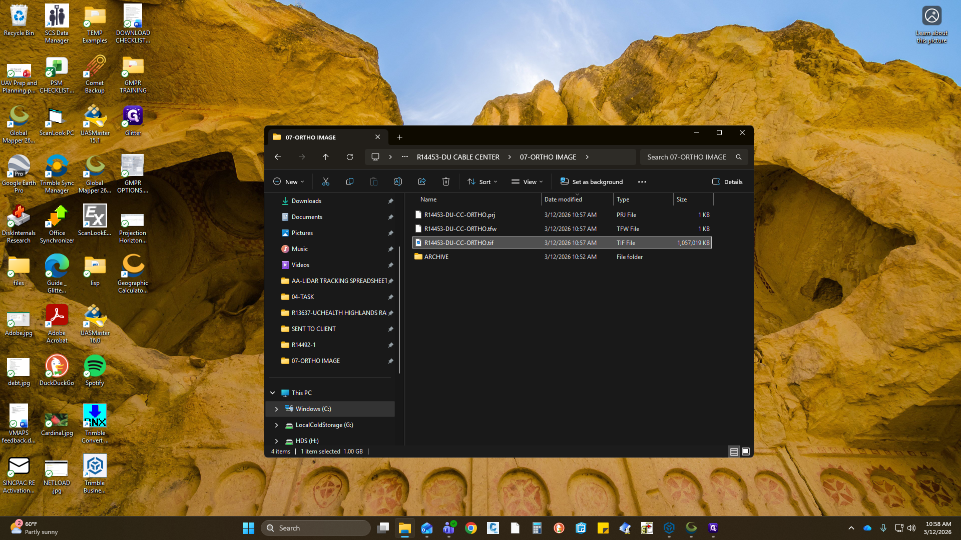
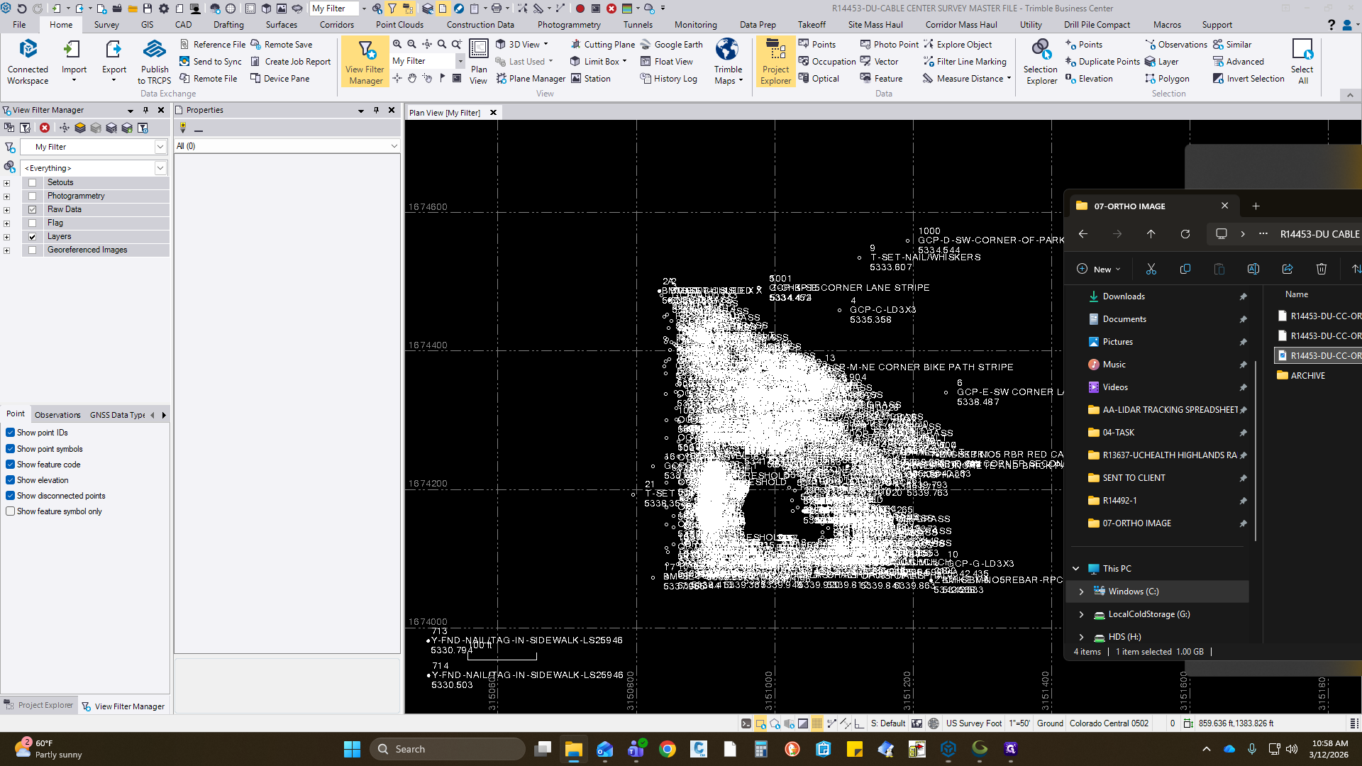
Remember, that was the PIX. Place it in our OrthoImage folder. Here, we should have the TIFF, the TFW, and the projection file. We are now exporting this with it because, in TPC, it was creating a translated file since it did not read the metadata or the projection. Make sure you have those three. I will grab this item and drag and drop it into TBC.
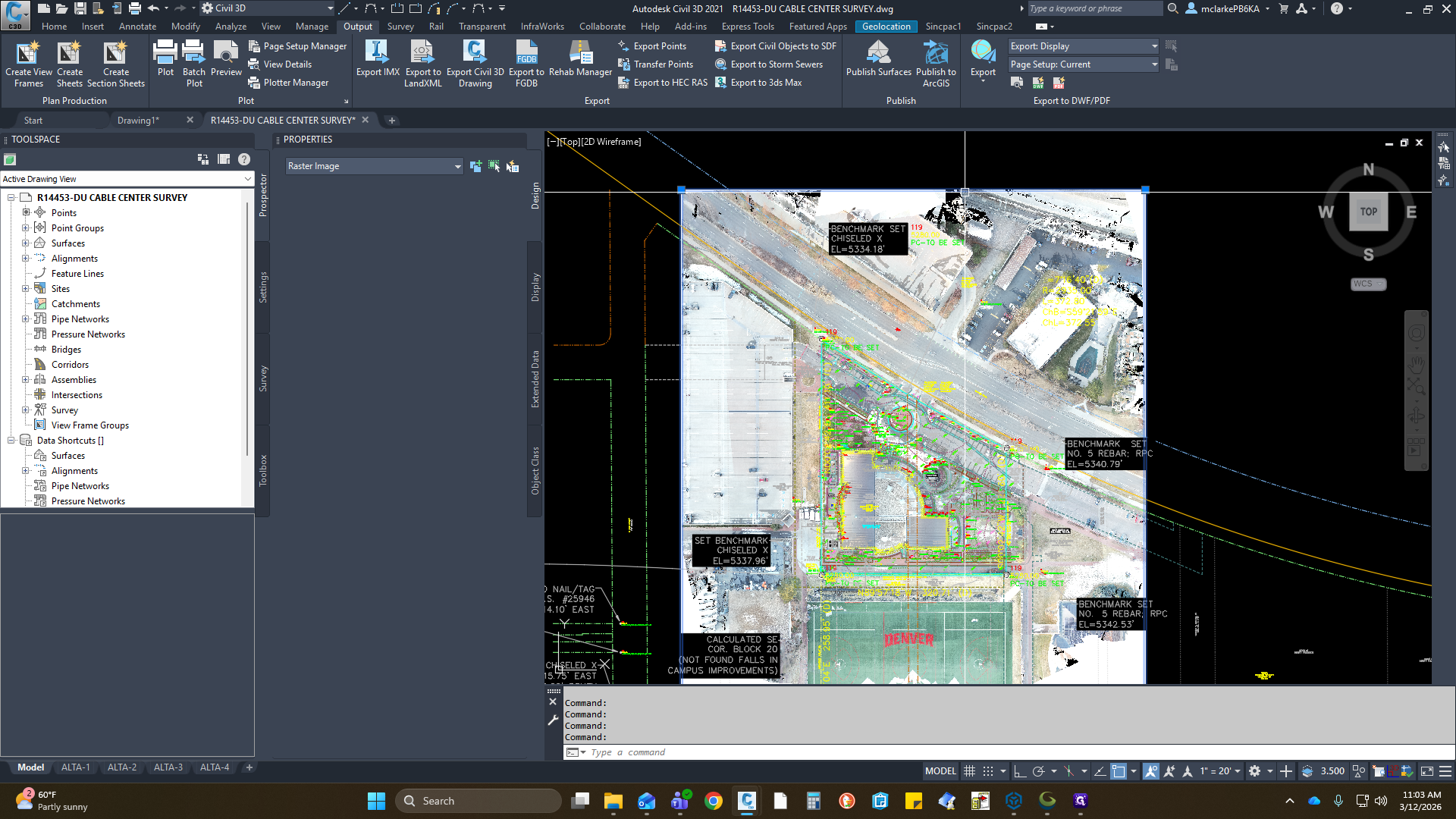
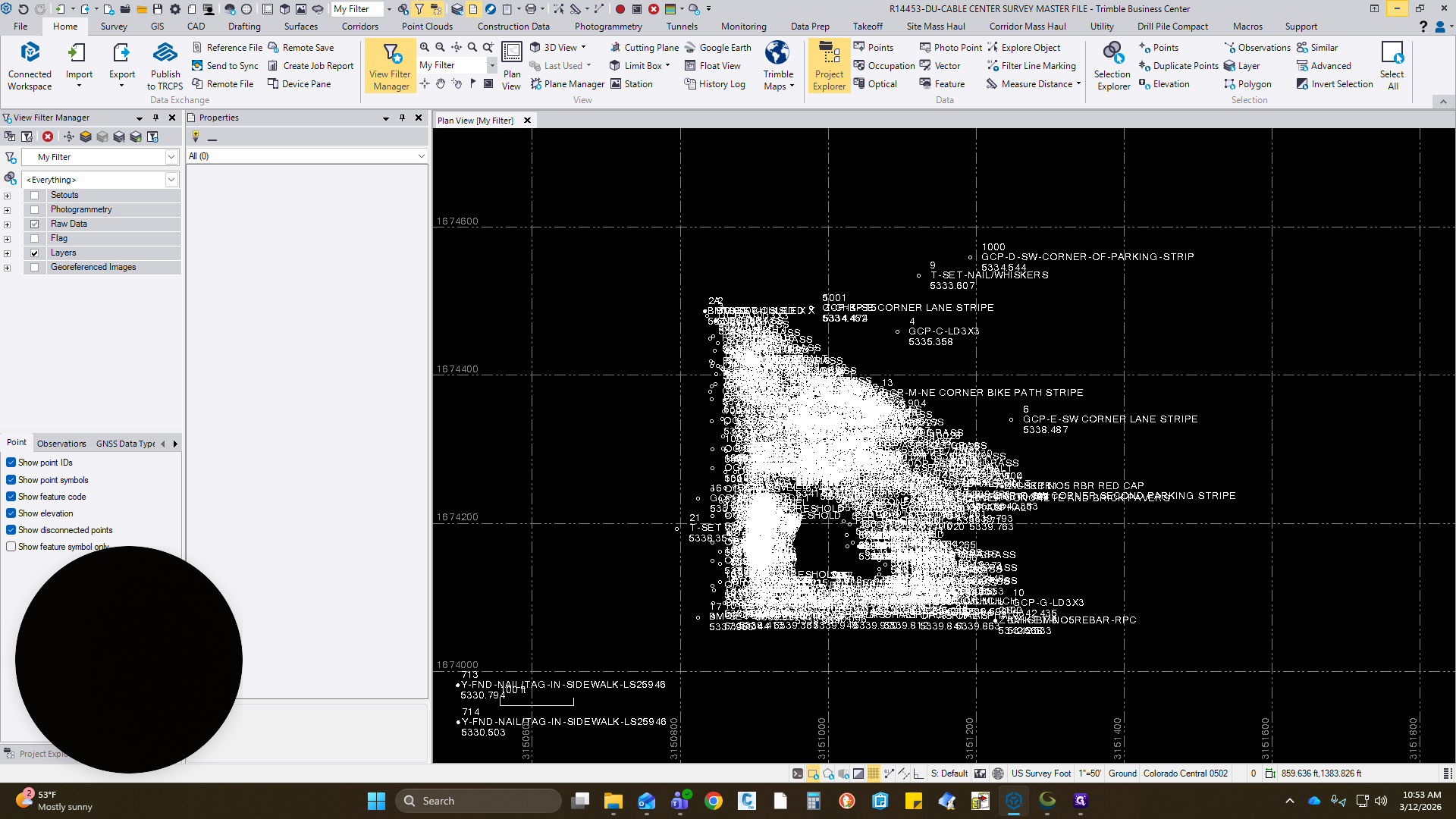
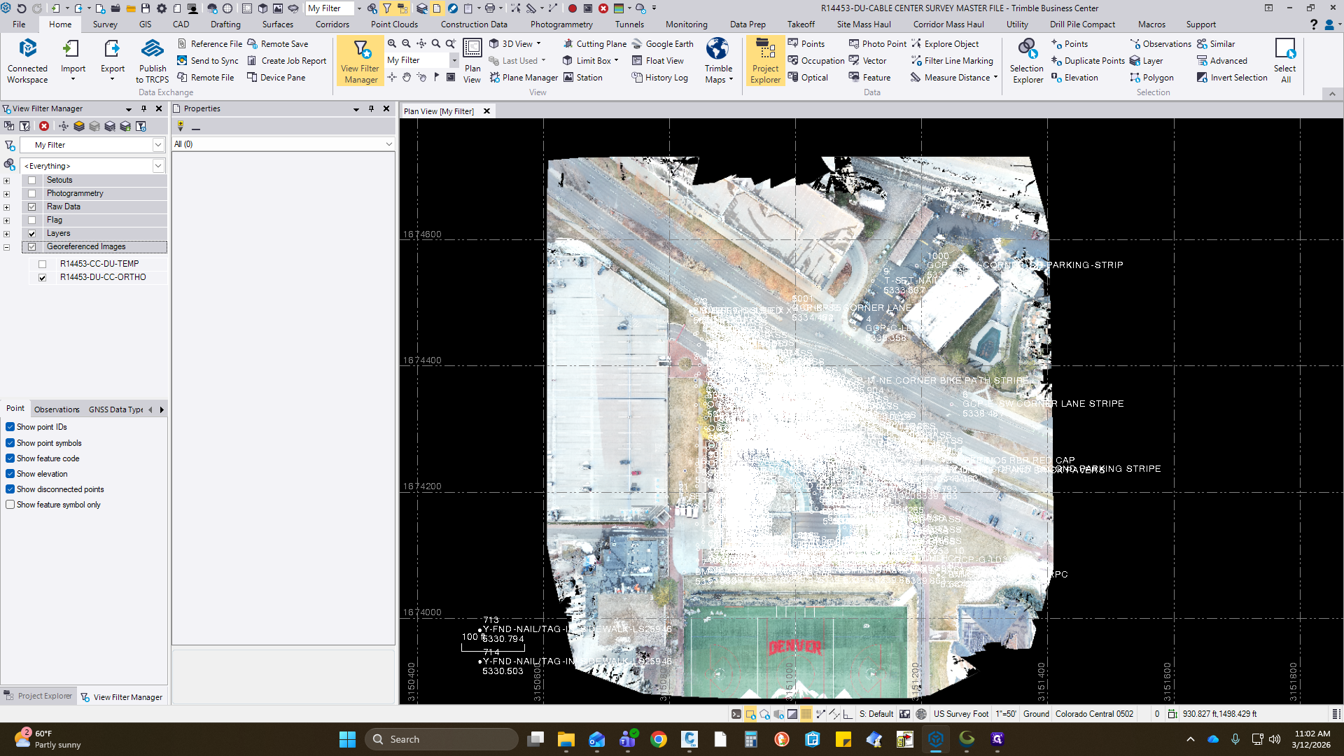
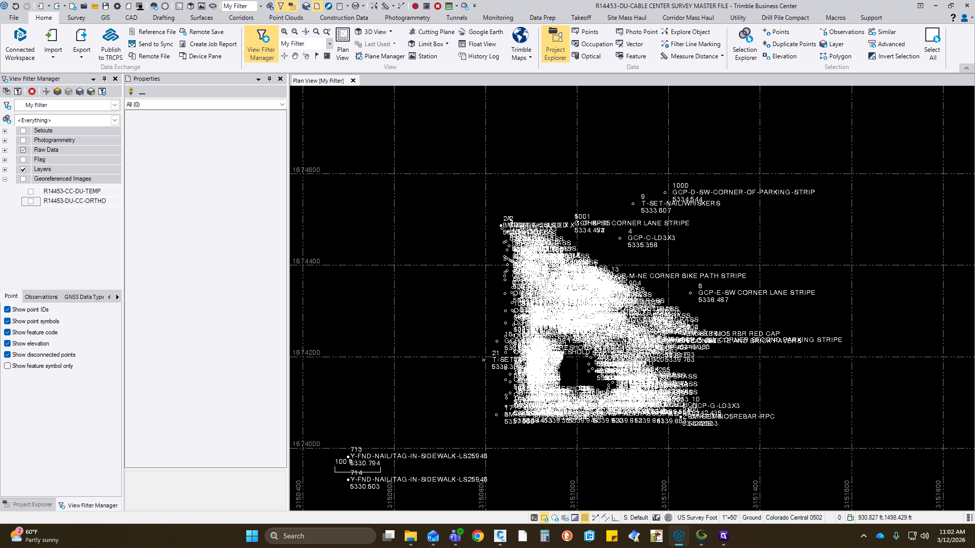
After importing into TBC, zoom in and check some of the GCPs to see if they align horizontally or have any major issues. 2D linework and concrete that you may see. This looks good. Everything is working correctly, so at this point, this should be here.
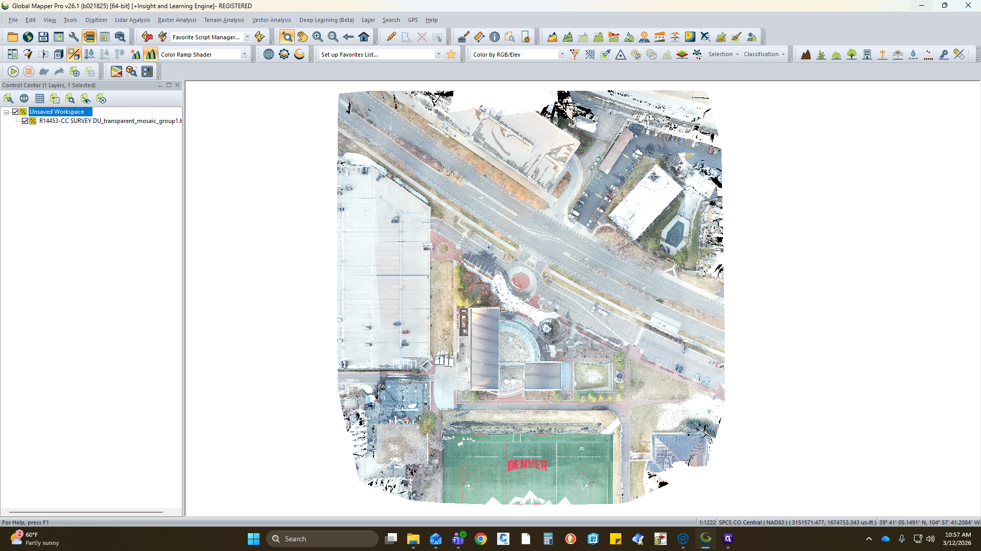
To the left is your image.

You can turn it on or off.
That is how you import into TBC. I will also show you how to import into CAD.

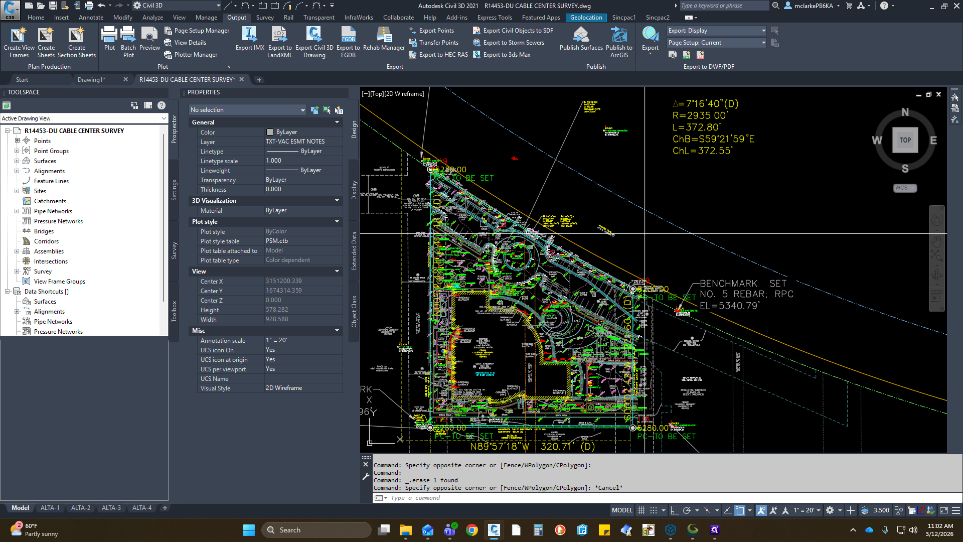
Hang on. Open the CAD drawing. Everything is included.

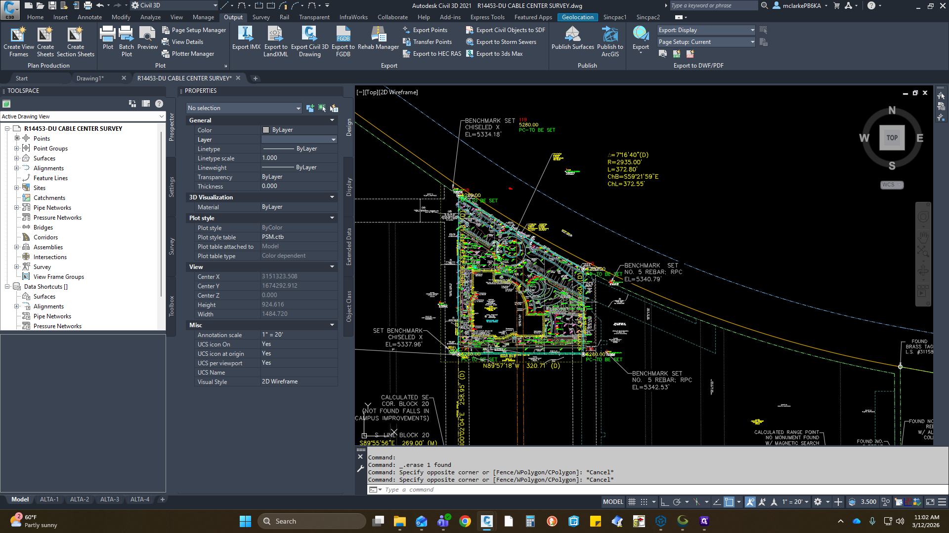
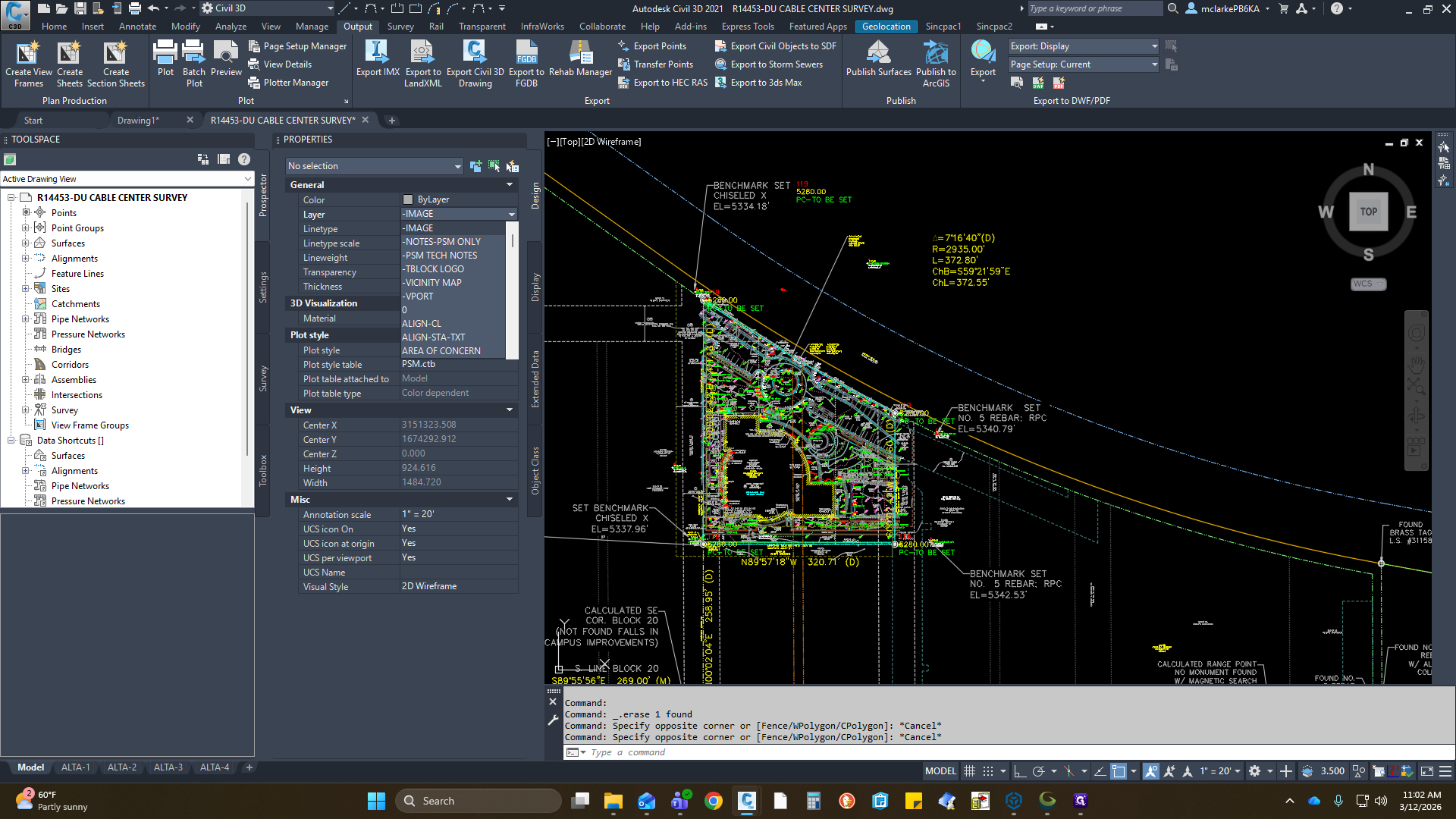
When importing, make sure you have the correct layer selected.
We have a dash image layer for this region.
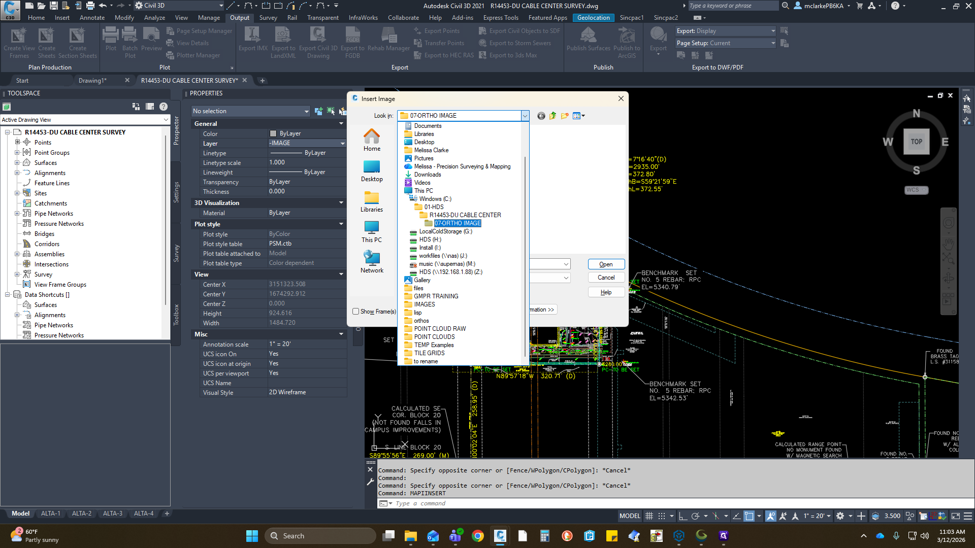
That will be a map insert, or the Insert key.
You can drive to your directory. Mine is set to C.
If someone is checking it, it's common to take it from the H.

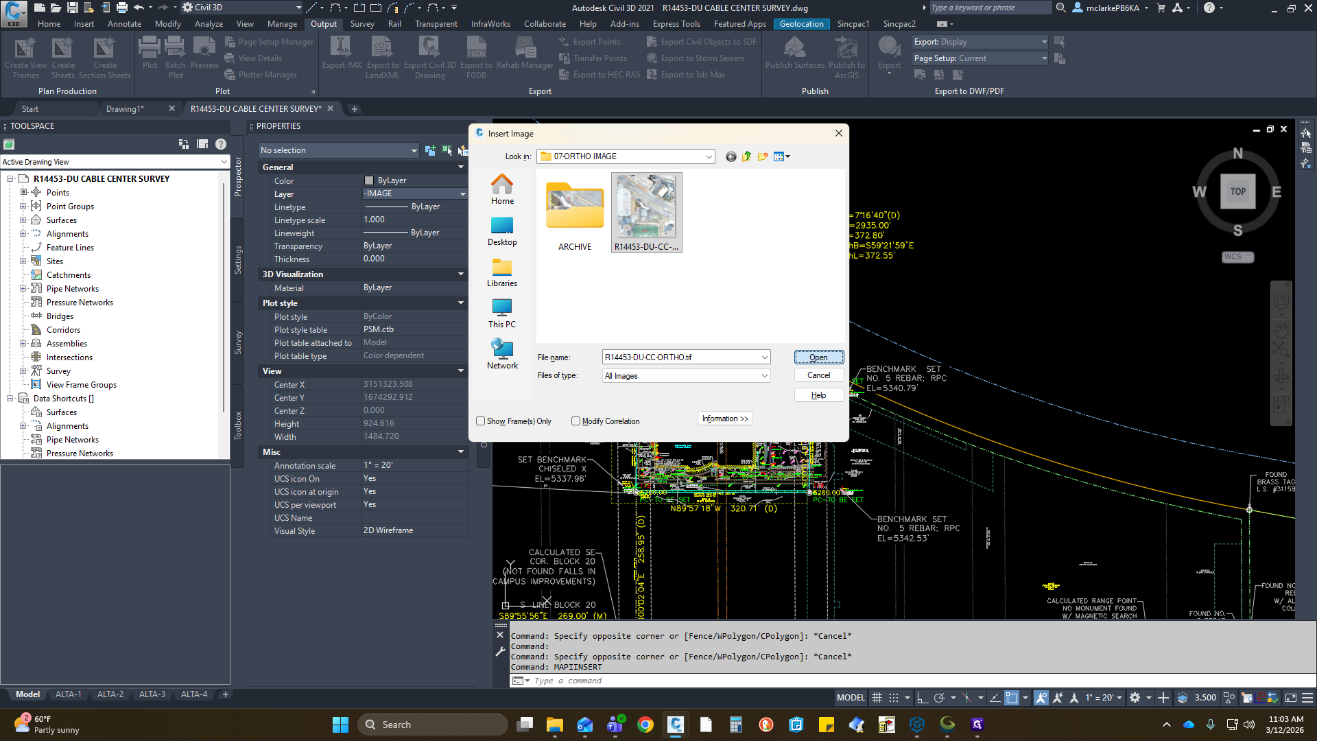
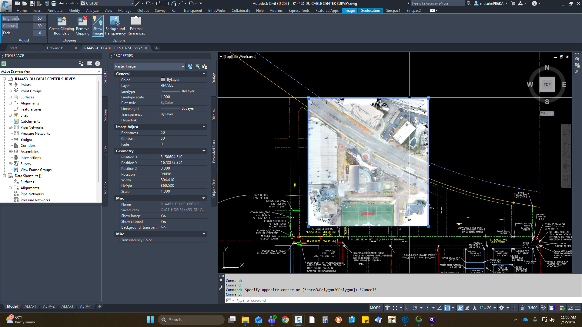
Here, we have our TIFF file. Click Open. It booted. I will display what I sent back. Next, look for horizontal confirmation to ensure it is hitting the correct spot.
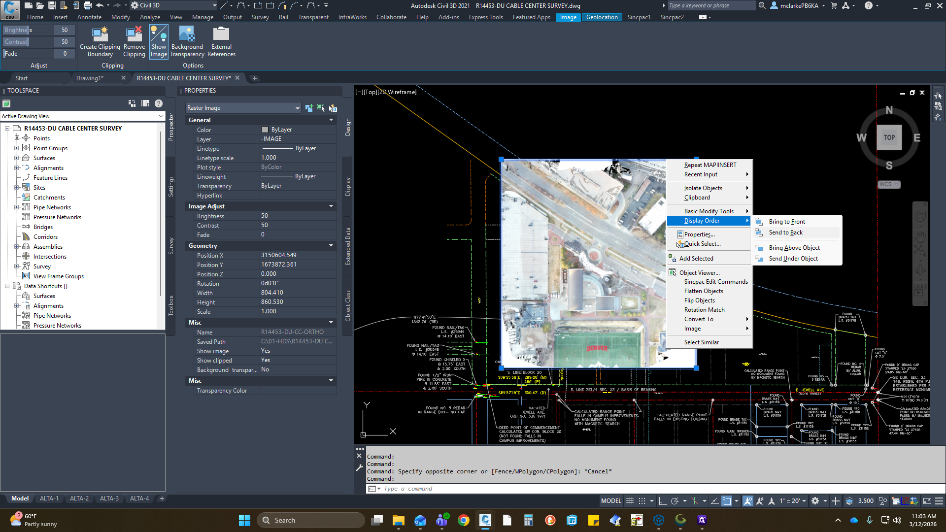
It looks good here. That is how you can import from Global Mapper into CAD. You have some other variables up here in the image, but that is it.


![Step #66: Click on "[ Fence / wPolygon / CPolygon ]"](https://di8mn0rali2ic.cloudfront.net/uploads/8de6b18a-0f5b-4a2b-8a64-fa4c4a54d39a/0f8cd30c-7fe9-4454-b84e-48021a36dd2e.png)