
How to Set Up a Multi-Photosphere Site on HP Rady: Part 2
Learn how to set up and configure multiple photospheres on HP Radii, including tips for accurate longitude and latitude placement, adjusting the mapping pane, and optimizing your project for better navigation.
In this guide, we'll learn how to set up and adjust the map view for a multi-photosphere project on HP Radii. We'll cover how to use longitude and latitude from Google Maps to position the mapping pane and set the viewport bearing and zoom level. This process helps ensure each photosphere is accurately placed and ready for further adjustments.
Let's get started
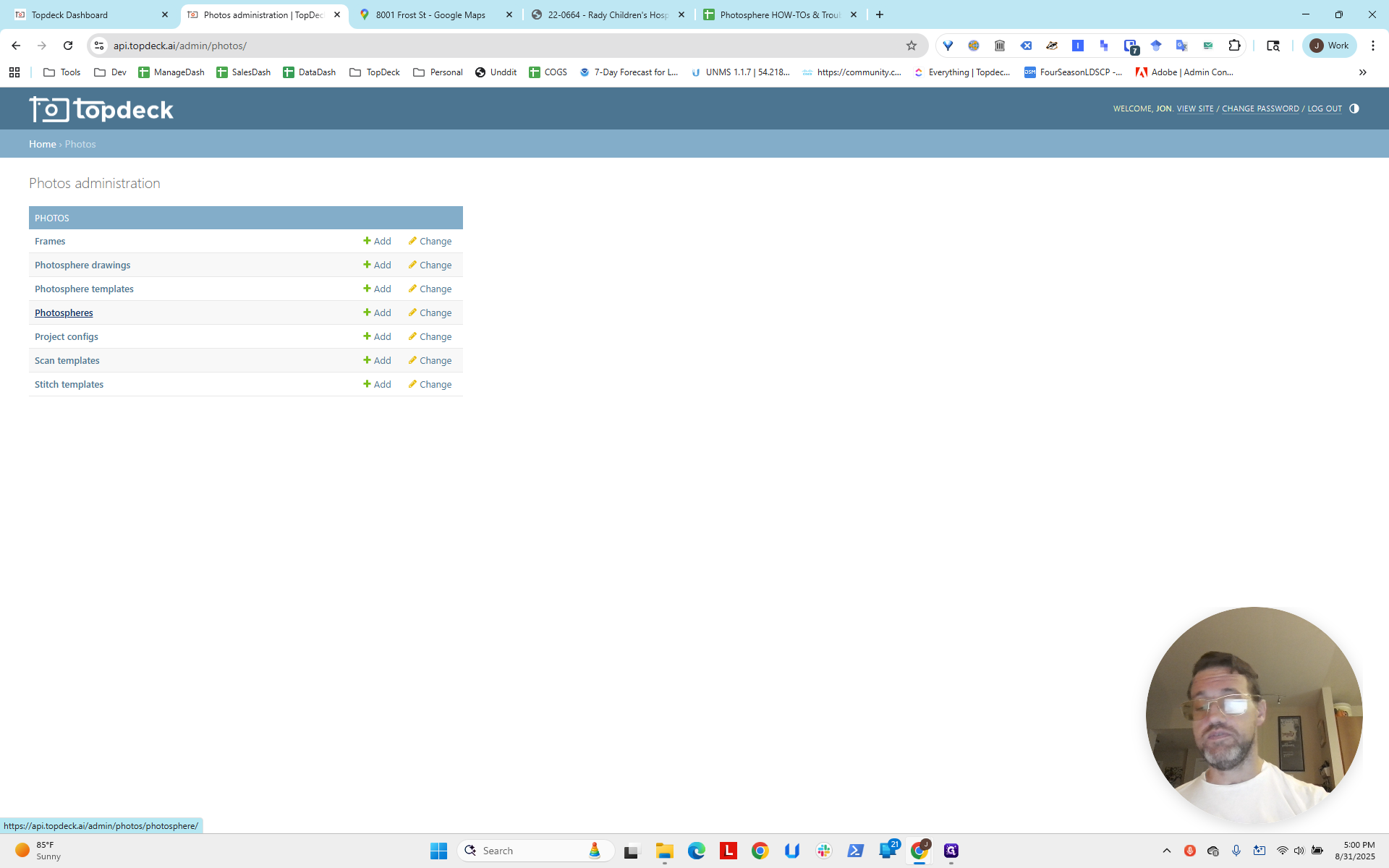
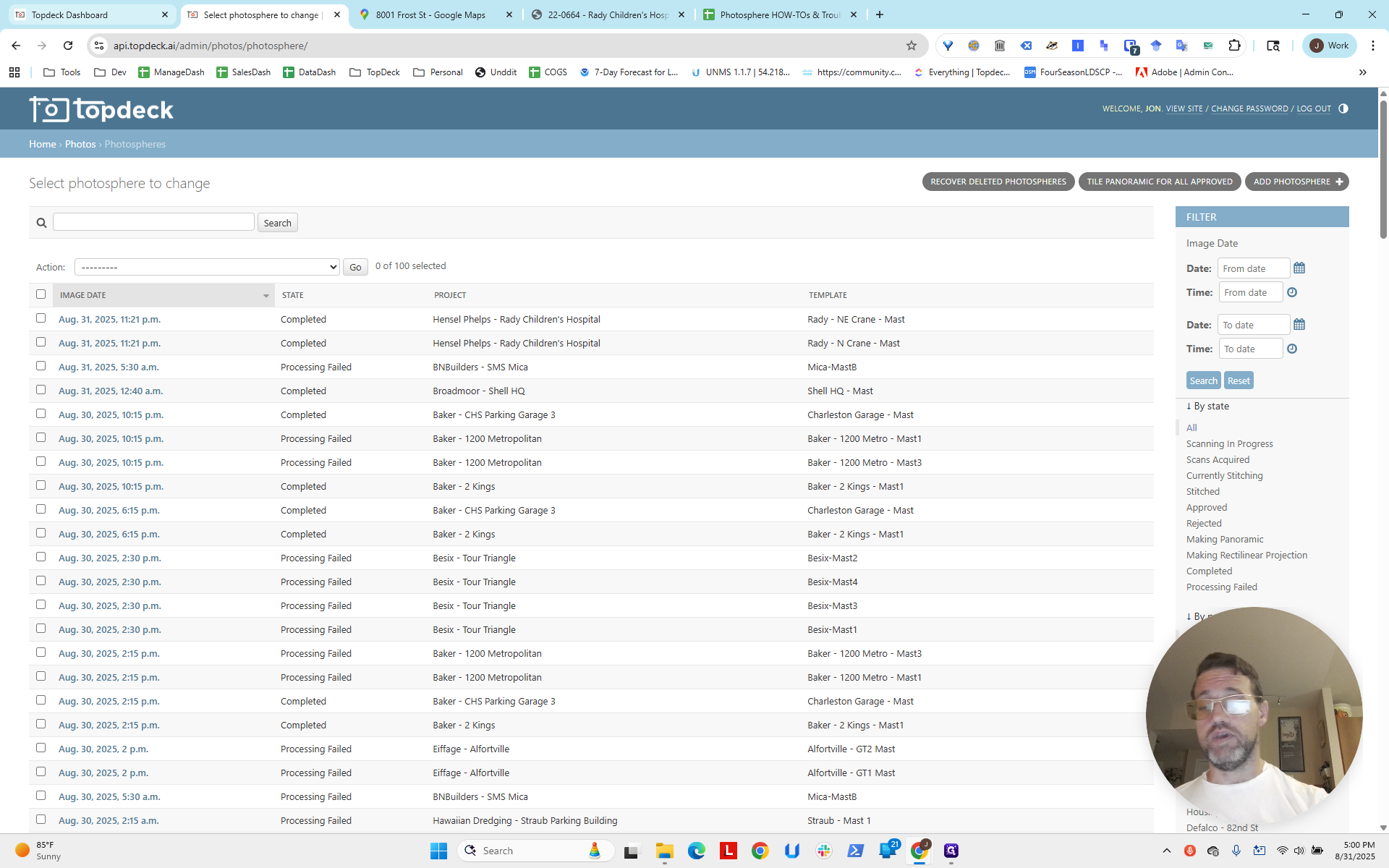
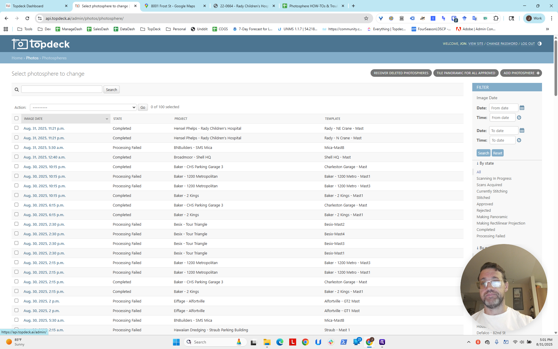
Hello, everyone. This is part two of setting up a multi-photosphere site on HP Radii. We've fast-forwarded about half an hour. If you go to the API and click on PhotoSpheres, you'll see that the two we created from the templates are now completed.

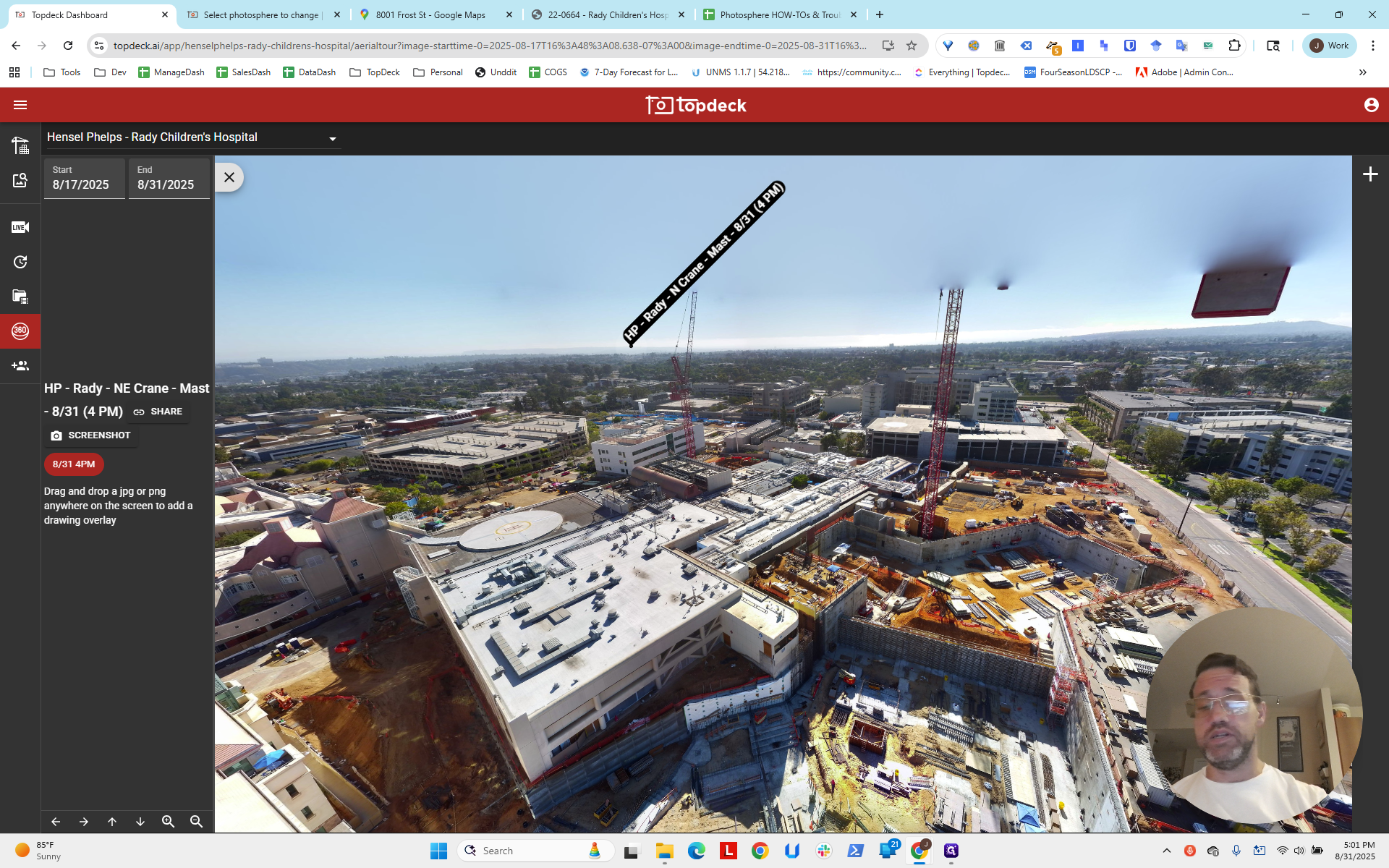
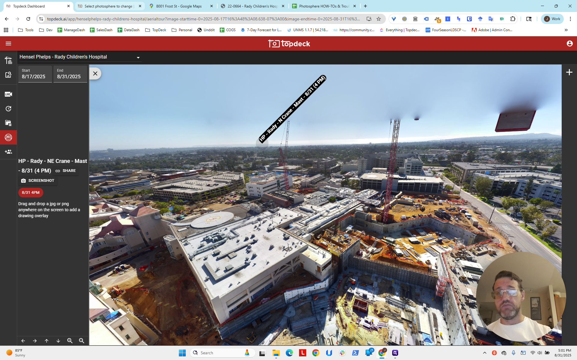
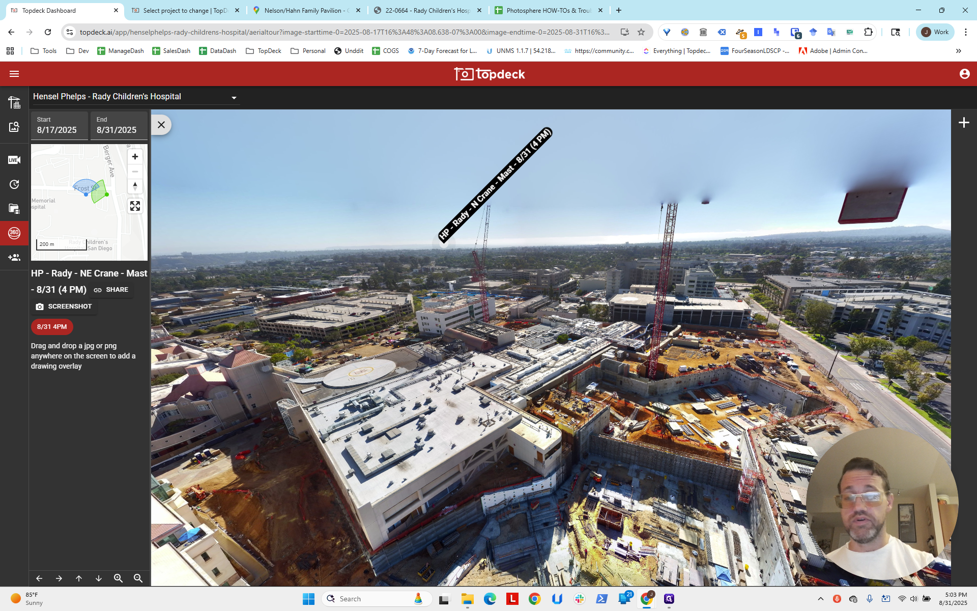
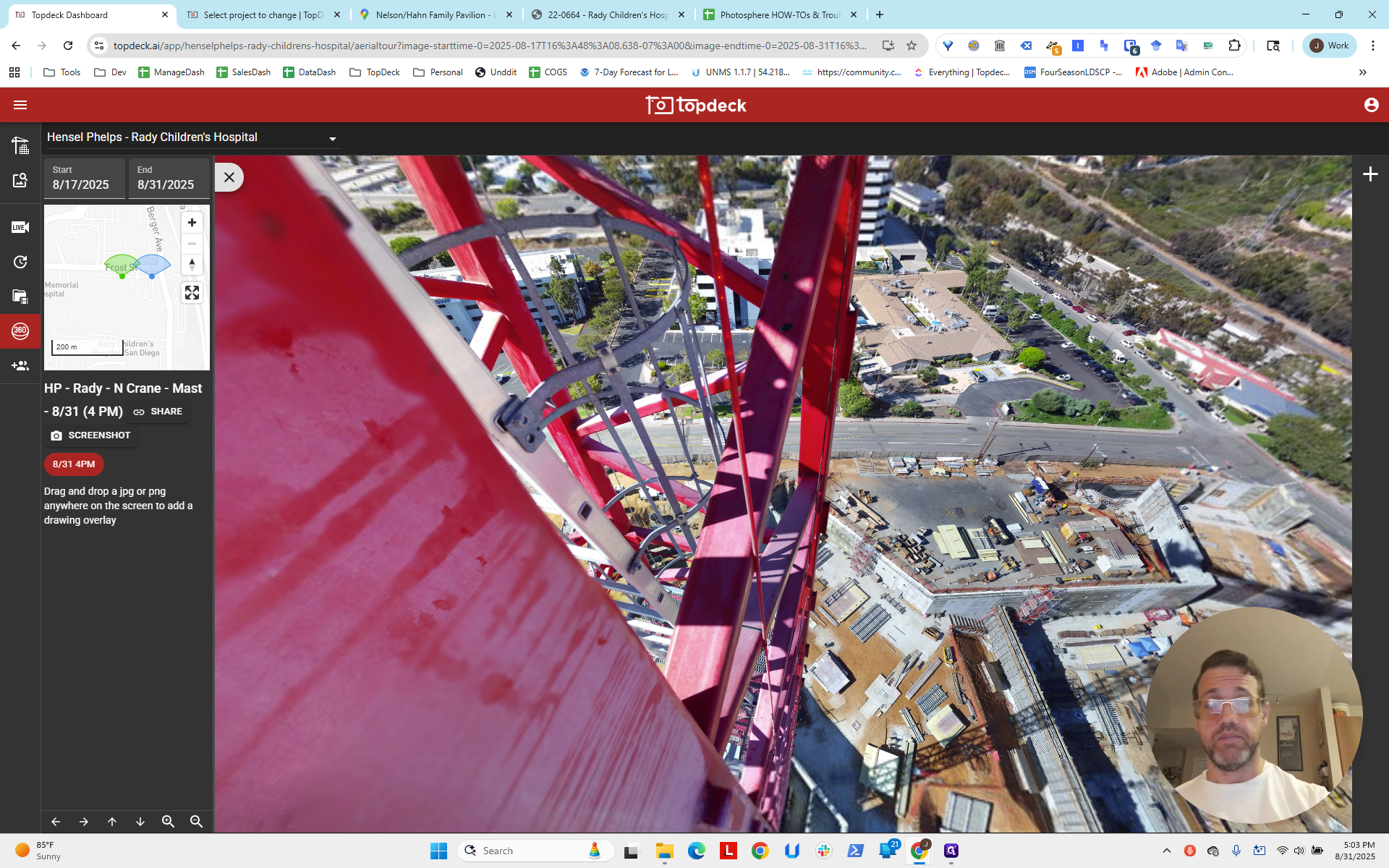
We can go to the project page and see that a photo sphere is available.
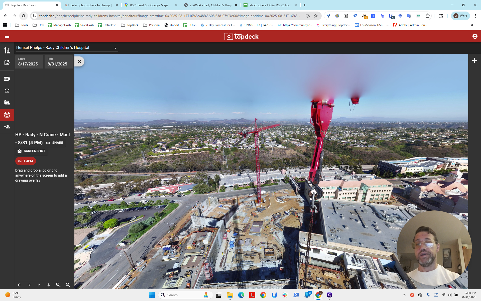
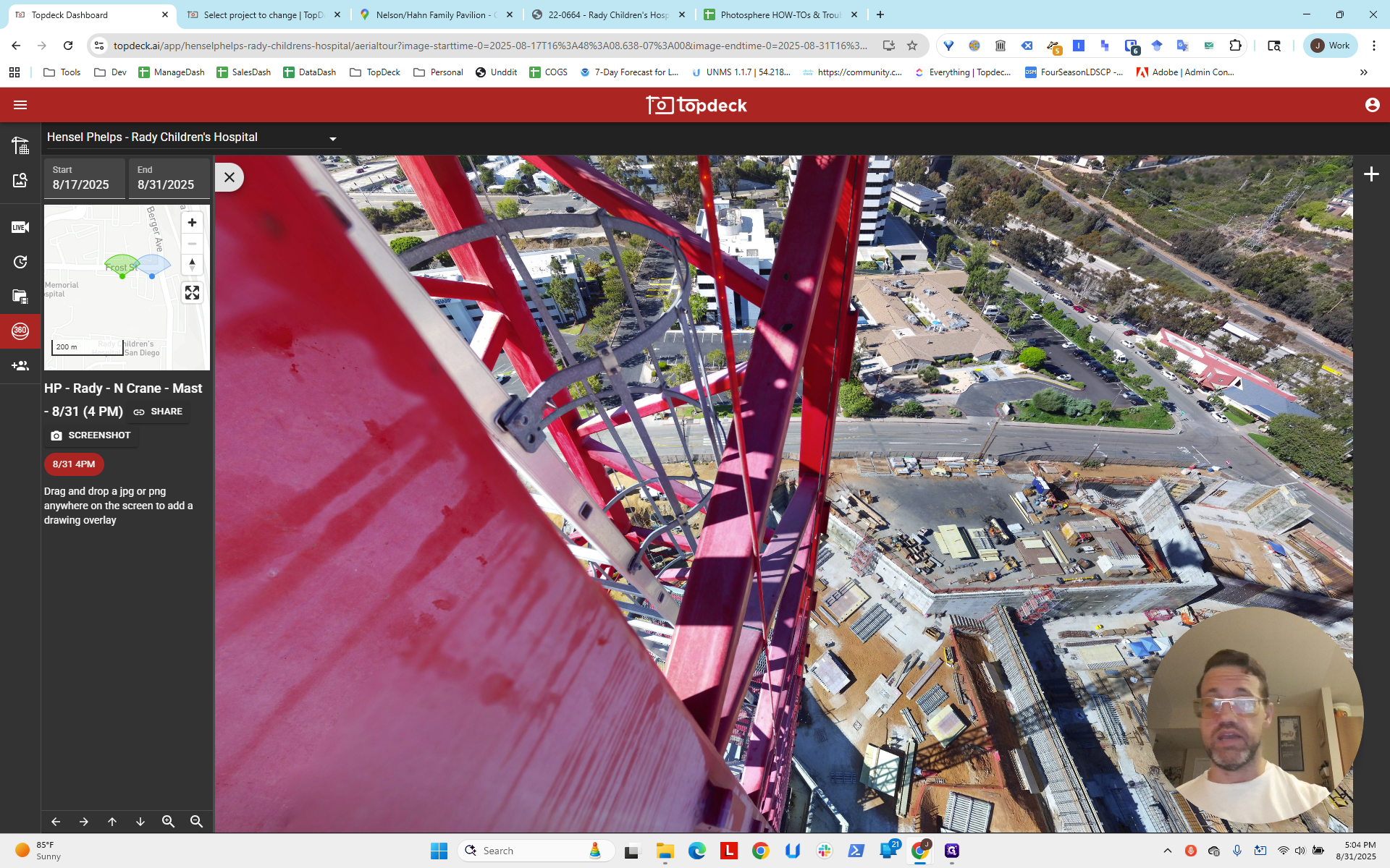
We can zoom in and move around to check for any issues. You can see there is a hot spot present here. It will orient itself based on the latitude and longitude coordinates we entered earlier. We were just guessing based on Google Maps. We will try to improve by using the intersection of two lines in the scene.
Two intersecting lines create a point. This lets us determine the camera's longitude and latitude. We'll cover that in the next video. For this, we're trying to set up the blank spot here where the map should be.
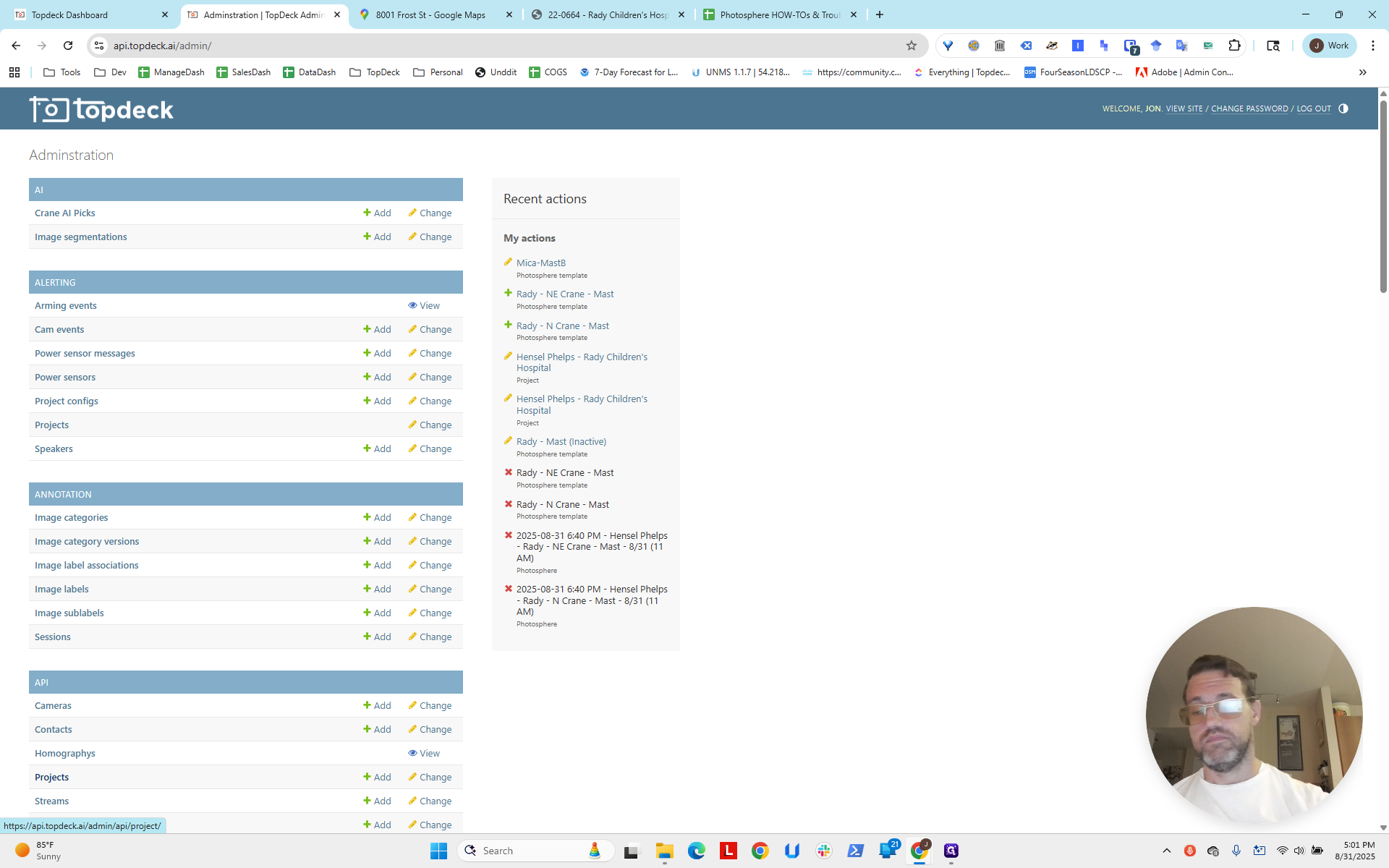
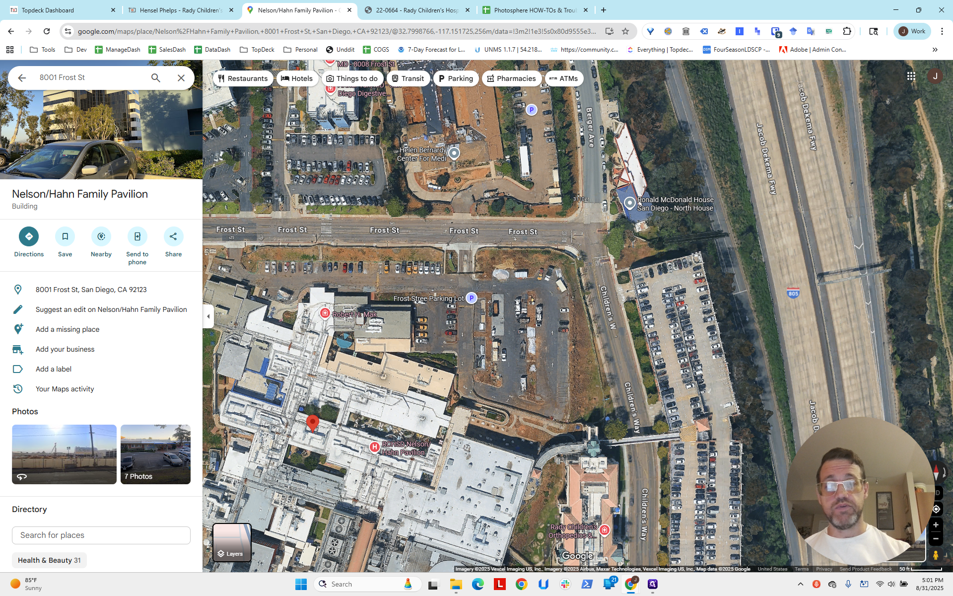
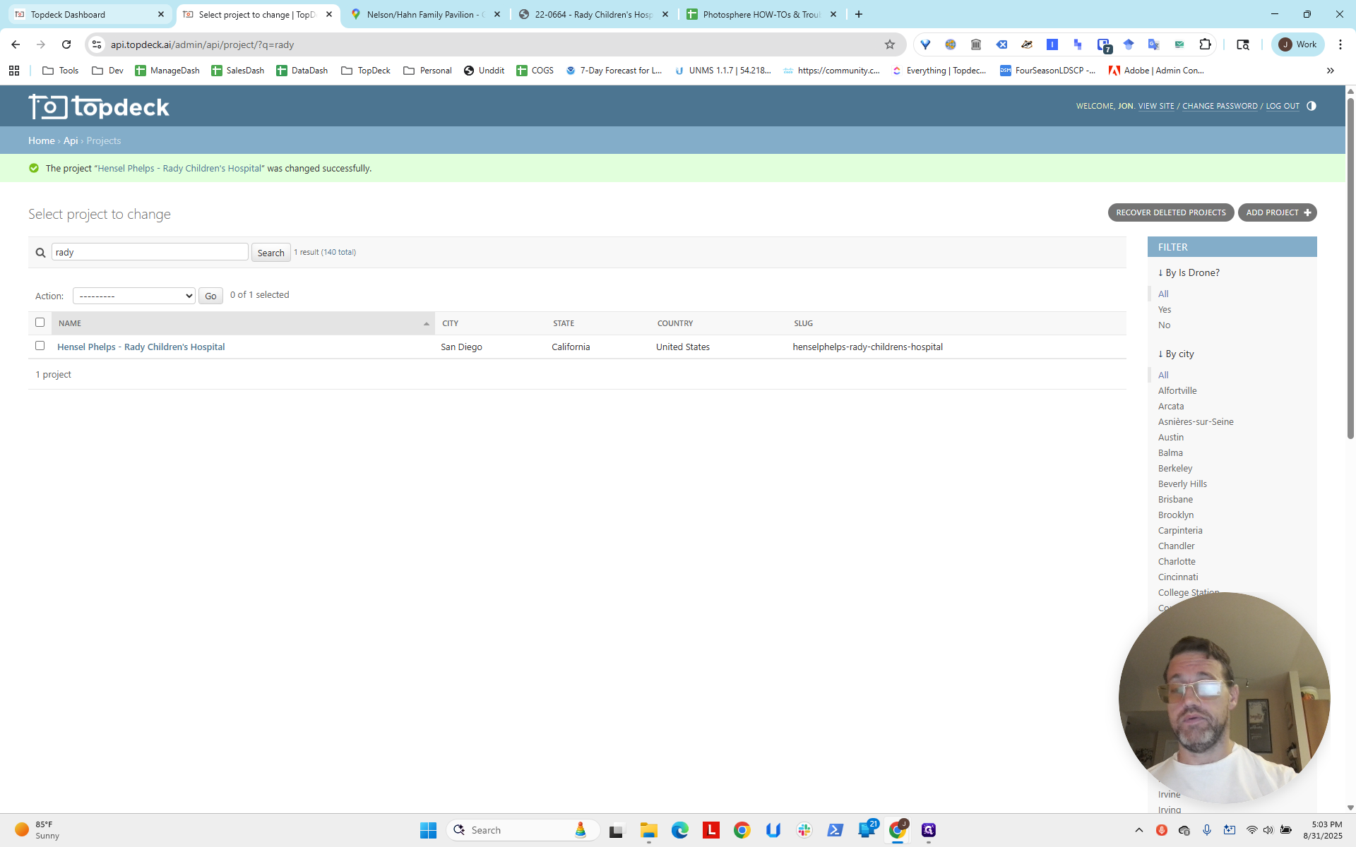
We will do that by modifying the project. We will go to the project.
We will type in "Radii."
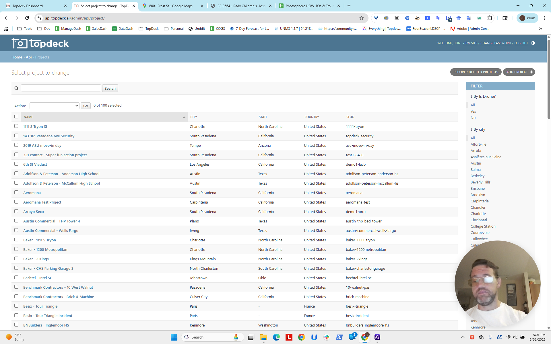
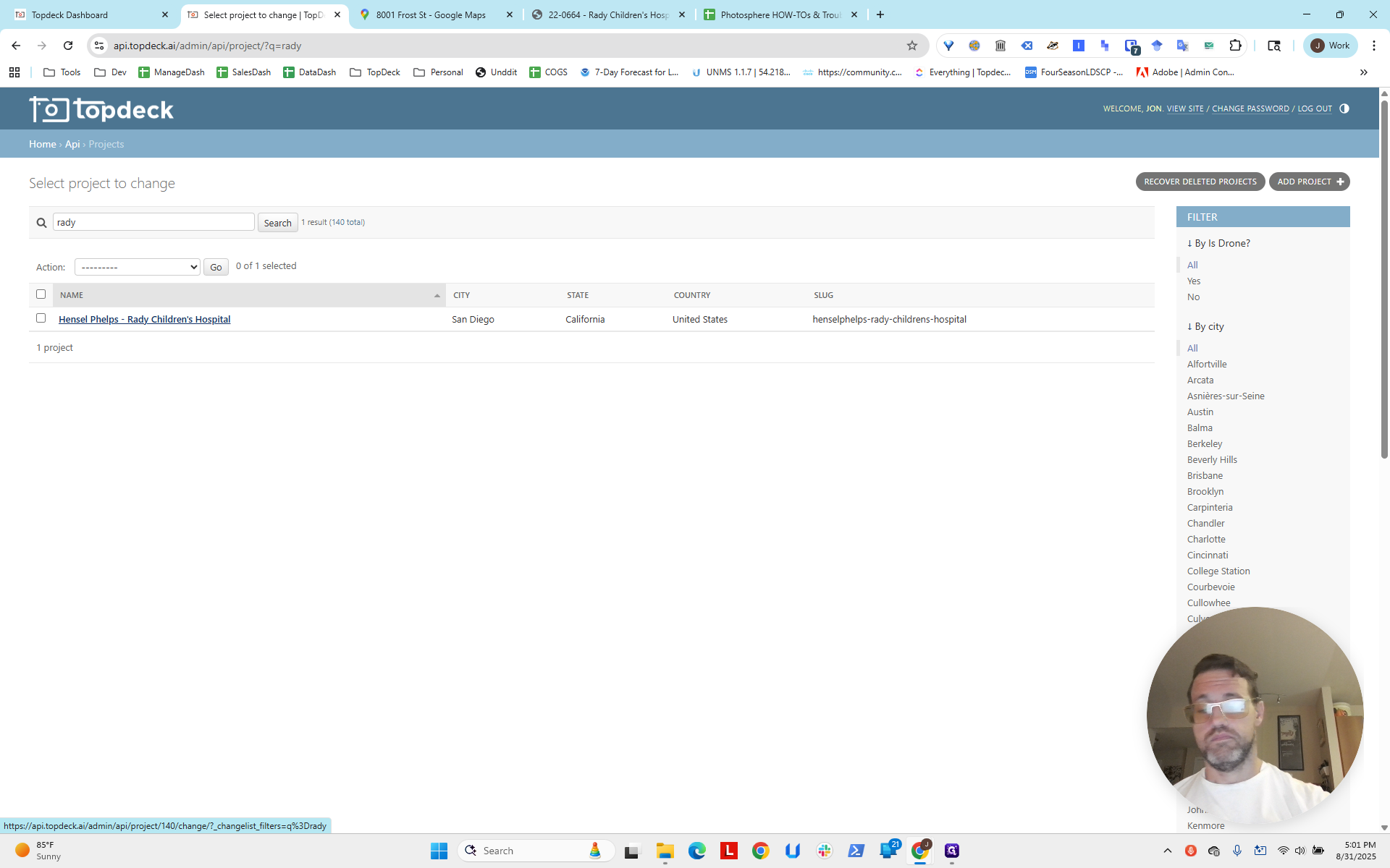
Now we're going to try, since we were just setting things up in this area before. Let's try to...
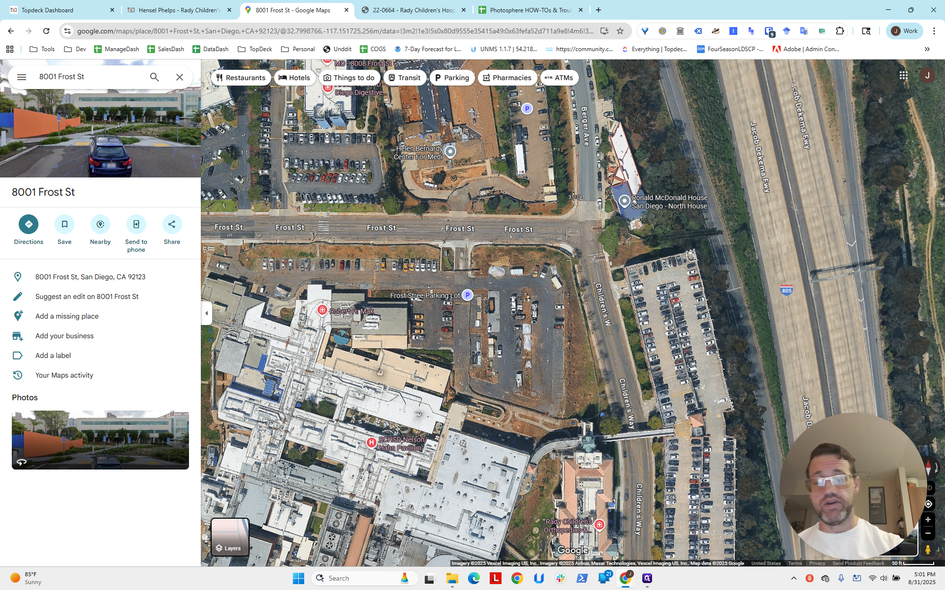
I'll right-click in the middle to get the longitude and latitude.
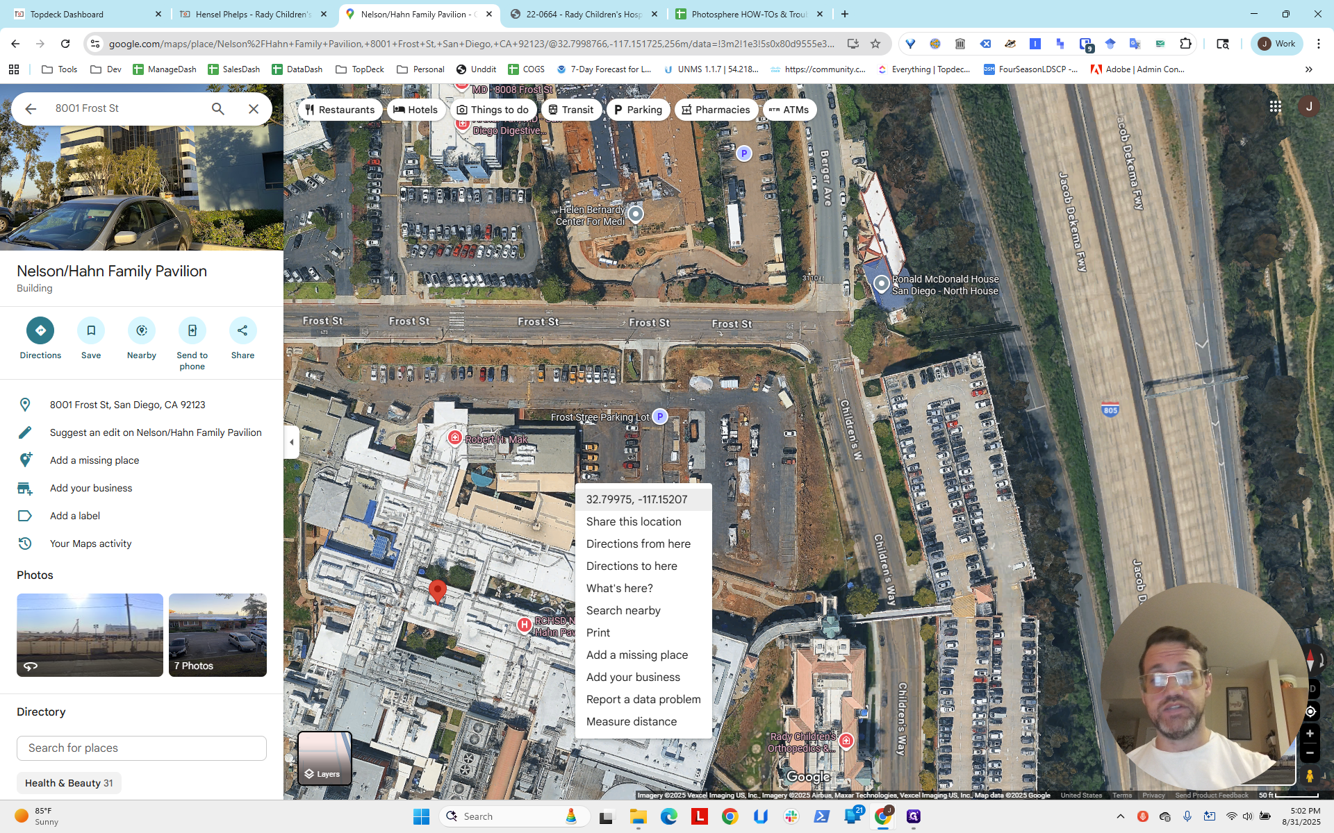
As with the others, we will correct this at the end, after fixing the individual photo spheres and their templates. This ensures we know their exact locations as accurately as possible. Then, we will move the mapping pane to center it, giving you enough space. Also, keep in mind there is a third crane located roughly where this red dot is. It will appear, so we need to consider it unless we want to go back and replace a mapping port.
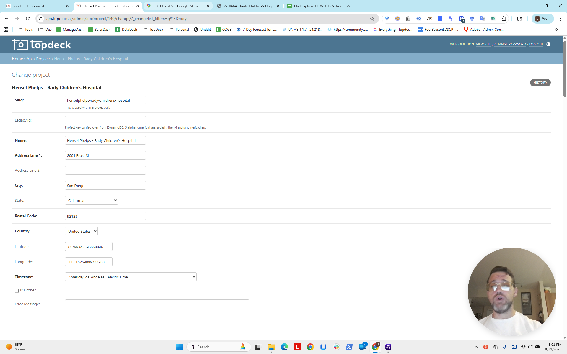
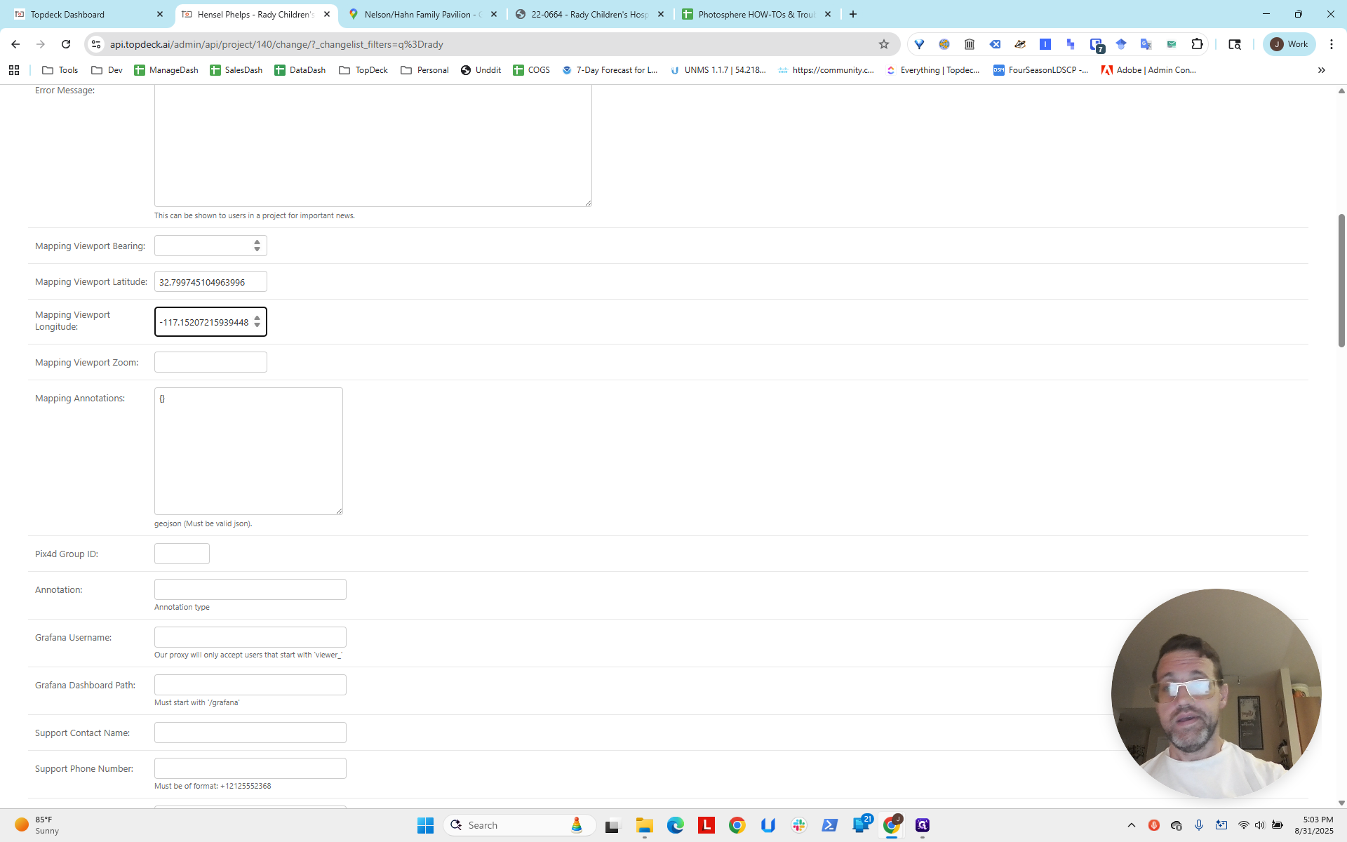
Back on the project page, we see the longitude and latitude, but we won't use them directly.
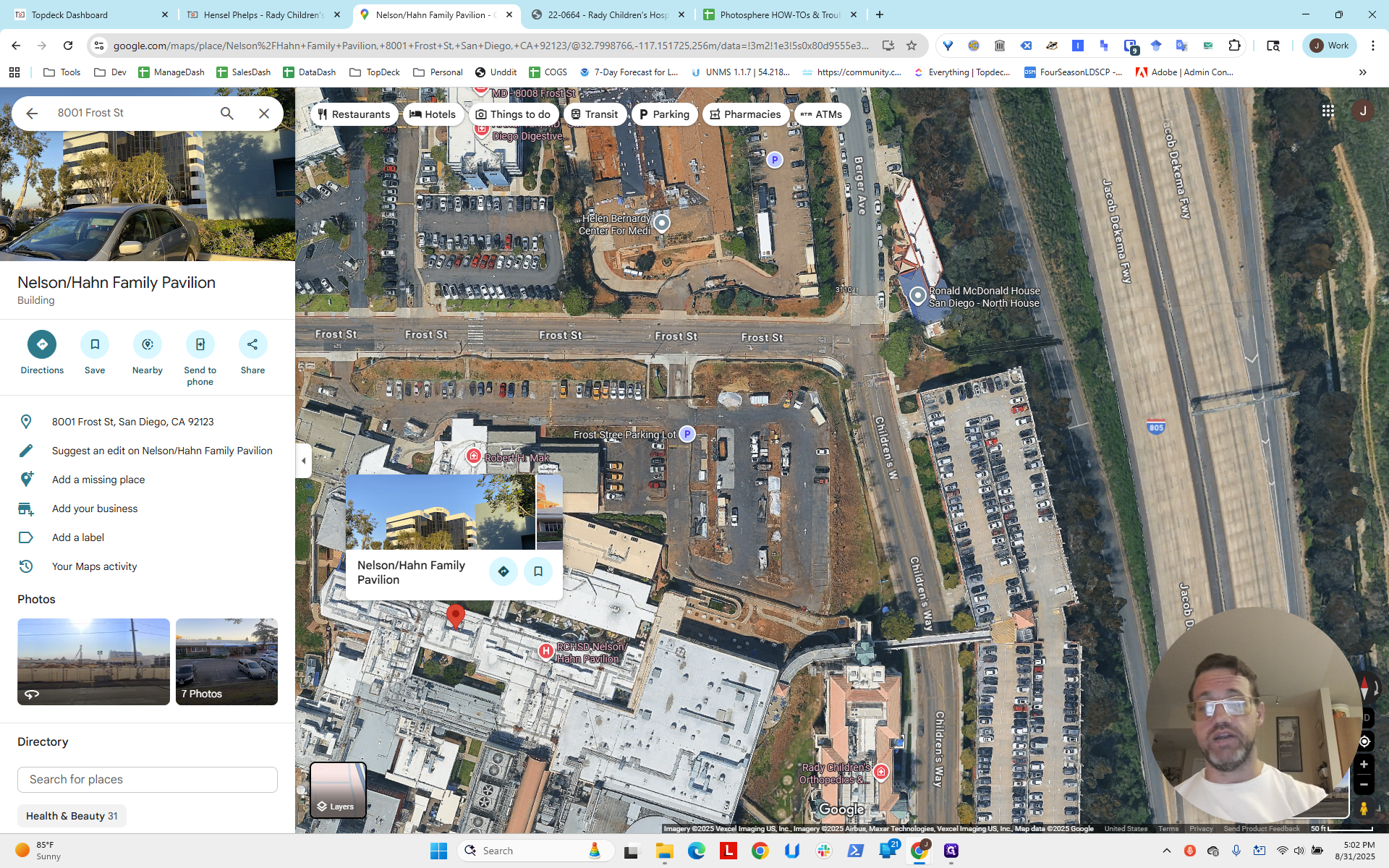
We're going to use what we used on Google Maps.
Here is the latitude, and here is the longitude.

It's the second number that doesn't copy over with a comma or space. For some reason, the period is deleted, so we'll add the period.
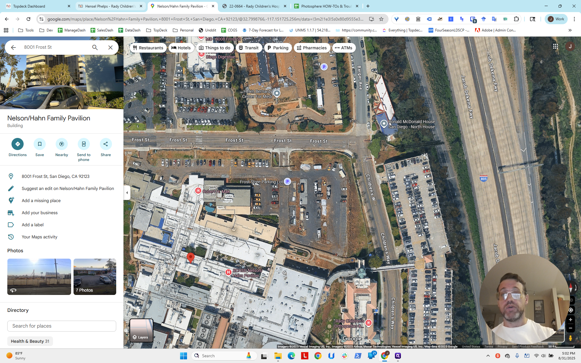
It depends on the size and scale of the project, as well as how far apart the cranes are. This is a good first step. That's all you need. Now, go to Save.
We return to the project, and here we are.
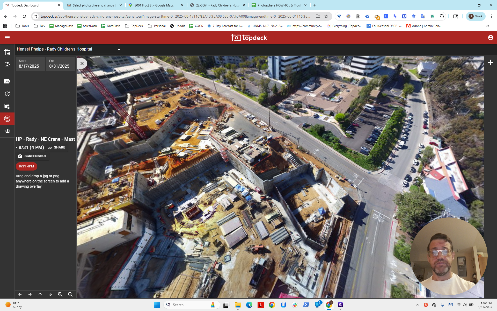
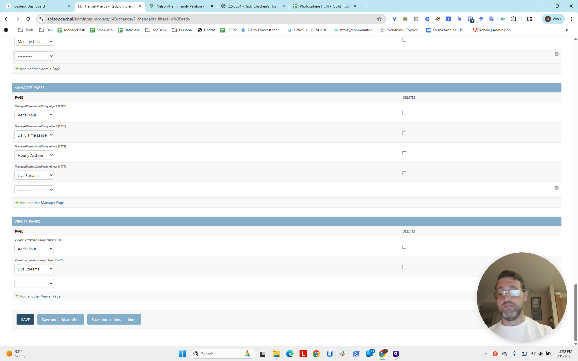
The viewing port is now visible, and we can click between the options.
We have it correct: one is to the northeast, and one is to the north. You can also see the viewing port.
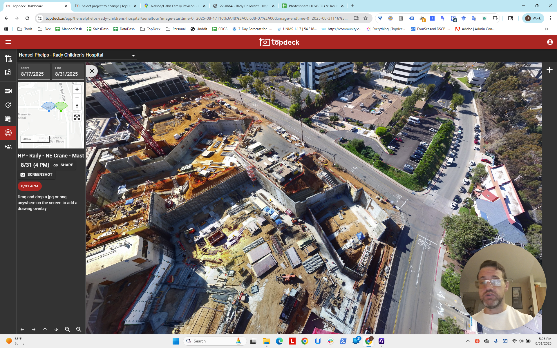
It's quite zoomed out. We'll likely need to zoom in, even when the third one is added below.
In the next video, we will go through and fix these items individually. We will ensure that HLookAt and ViewLookAt are set correctly, adjust the cones so the bearing is accurate, and confirm everything is set properly.


As a general rule, start at 12. Then, increase the number to zoom in further. Sometimes it's 16, and sometimes it's 18.


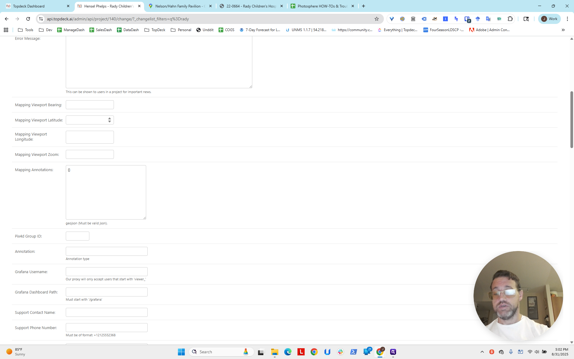
Next, set the Viewport Bearing to 0. We will adjust the zoom later.
Okay.